Gigabyte GA-Z68AP-D3 Manual - Page 28
F_USB1/F_USB2/F_USB3 USB 2.0/1.1 Headers, TPM Trusted Platform Module Header
 |
View all Gigabyte GA-Z68AP-D3 manuals
Add to My Manuals
Save this manual to your list of manuals |
Page 28 highlights
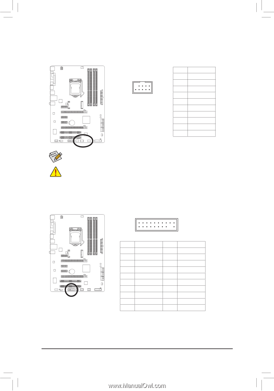
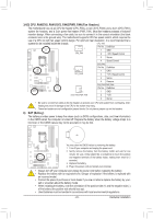
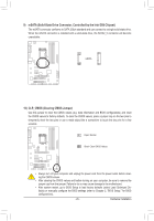
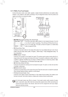
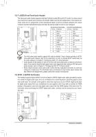
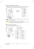
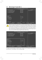
14) F_USB1/F_USB2/F_USB3 (USB 2.0/1.1 Headers) The headers conform to USB 2.0/1.1 specification. Each USB header can provide two USB ports via an UG T optional USB bracket. For purchasing the optional USB bracket, please contact the local dealer. 9 10 F_USB30 Pin No. Definition 1 Power (5V) 2 Power (5V) 1 2 3 USB DX- 4 USB DY- 5 USB DX+ 6 USB DY+ 7 GND 8 GNFD_AUDIO(H) 9 No Pin 10 NC When the system is in S4/S5 mode, only the USB ports routed to the F_USB1 header can support the ON/OFF Charge function. •• Do not plug the IEEE 1394 bracket (2x5-pin) cable into the USB header. •• Prior to installing the USB bracket, be sure to turn off your computer and unplug the power cord from the power outlet to prevent damage to the USB bracket. DB_PORT 15) TPM (Trusted Platform Module Header) You may connect a TPM (Trusted Platform Module) to this header. 1 BIOS Switcher 1 1 19 TPM w/housing 20 Pin No. 1 2 3 4 5 6 7 8 9 10 Definition LCLK GND LFRAME No Pin LRESET NC LAD3 LAD2 VCC3 LAD1 1 Voltage measurement module(X58A-OC) PWM Switch DIP 1 23 2 DIP Pin No. Definition 1 23 11 LAD0 PCIe power connector (SATA)(X58A-OC) 12 GND 13 NC 14 ID 15 SB3V 16 SERIRQ 17 GND 18 NC 19 NC 20 SUSCLK Hardware Installation - 28 -
-
 1
1 -
2
-
3
-
4
-
5
-
6
-
7
-
8
-
9
-
10
-
11
-
12
-
13
-
14
-
15
-
16
-
17
-
18
-
19
-
20
-
21
-
22
-
 23
23 -
 24
24 -
 25
25 -
 26
26 -
 27
27 -
 28
28 -
 29
29 -
 30
30 -
 31
31 -
 32
32 -
 33
33 -
34
-
35
-
36
-
37
-
38
-
39
-
40
-
41
-
42
-
43
-
44
-
45
-
46
-
47
-
48
-
49
-
50
-
51
-
52
-
53
-
54
-
55
-
56
-
57
-
58
-
59
-
60
-
61
-
62
-
63
-
64
-
65
-
66
-
67
-
68
-
69
-
70
-
71
-
72
-
73
-
74
-
75
-
76
-
77
-
78
-
79
-
80
-
81
-
82
-
83
-
84
-
85
-
86
-
87
-
88
-
89
-
90
-
91
-
92
-
93
-
94
-
95
-
96
-
97
-
98
-
99
-
100
-
101
-
102
-
103
-
104
 |
 |