Gigabyte GA-Z68X-UD3H-B3 Manual - Page 32
TPM Trusted Platform Module Header, PHASE LED, Refer to Dynamic Energy Saver
 |
UPC - 818313013132
View all Gigabyte GA-Z68X-UD3H-B3 manuals
Add to My Manuals
Save this manual to your list of manuals |
Page 32 highlights
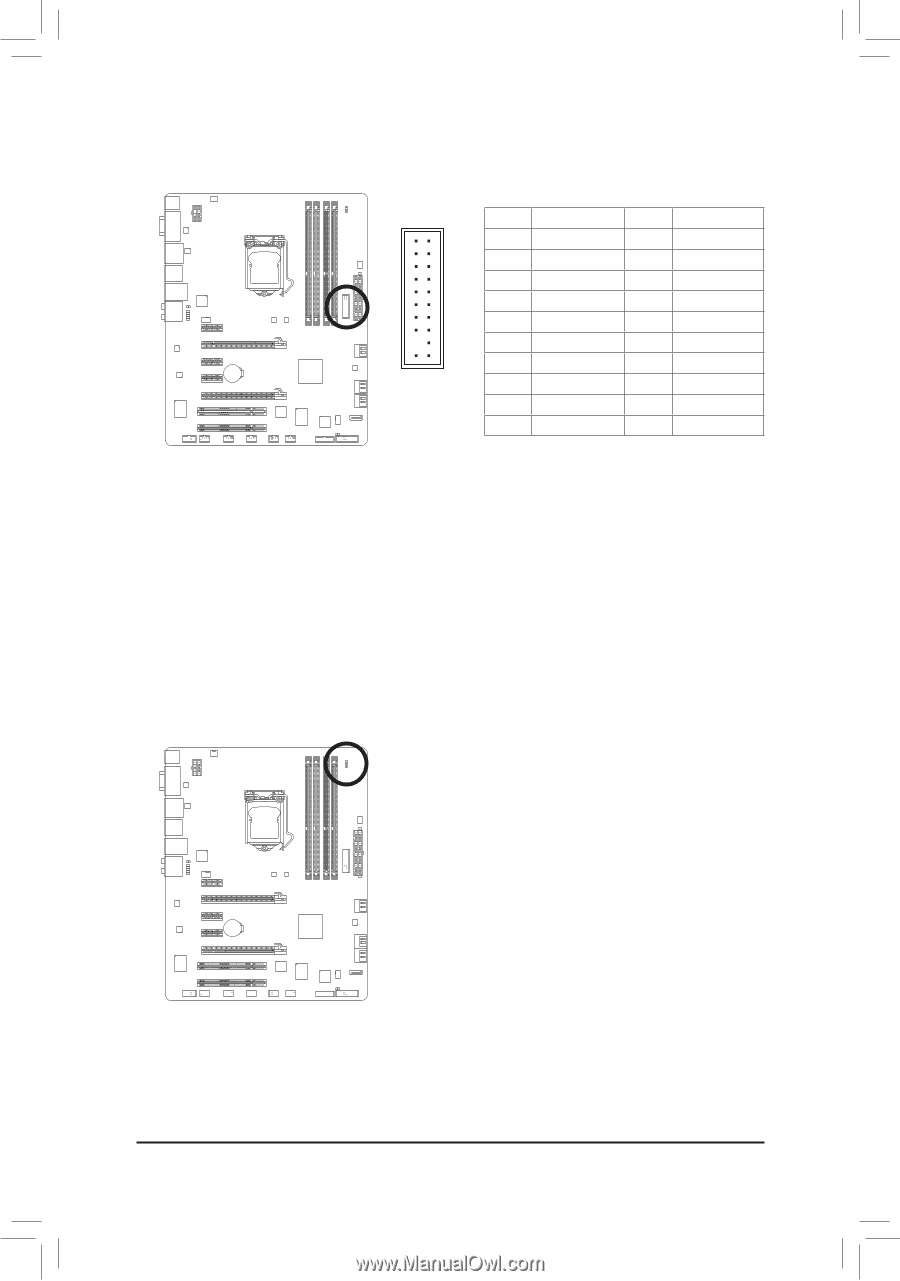
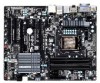
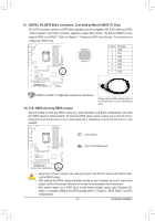
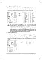
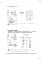
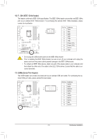
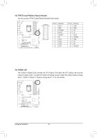
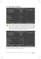
1 DIP 1 23 1 DIP 1 23 1 TPM w/housing Voltage measurement module(X58A-OC) 18) TPM (Trusted Platform Module Header) You may connect a TPM (Trusted Platform Module) to this header. DIP 1 23 PWM Switch (X58A-OC) DIP 1 23 PinPNCIoe.powDeer fcinonitnioenctor (SATA)P(Xin58NAo-O. C)Definition 20 19 1 LCLK 11 LAD0 2 GND 12 GND 3 LFRAME 13 NC 4 No Pin 14 ID 5 LRESET 15 SB3V 6 NC 2 1 7 LAD3 16 SERIRQ 17 GND 8 LAD2 18 NC 9 VCC3 19 NC 10 LAD1 20 SUSCLK 19) PHASE LED The number of lighted LEDs indicates the CPU loading. The higher the CPU loading, the more the number of lighted LEDs. To enable the Phase LED display function, please first enable Dynamic Energy Saver™ 2. Refer to Chapter 4, "Dynamic Energy Saver™ 2," for more details. Hardware Installation - 32 -
-
 1
1 -
2
-
3
-
4
-
5
-
6
-
7
-
8
-
9
-
10
-
11
-
12
-
13
-
14
-
15
-
16
-
17
-
18
-
19
-
20
-
21
-
22
-
23
-
24
-
25
-
26
-
 27
27 -
 28
28 -
 29
29 -
 30
30 -
 31
31 -
 32
32 -
 33
33 -
 34
34 -
 35
35 -
 36
36 -
 37
37 -
38
-
39
-
40
-
41
-
42
-
43
-
44
-
45
-
46
-
47
-
48
-
49
-
50
-
51
-
52
-
53
-
54
-
55
-
56
-
57
-
58
-
59
-
60
-
61
-
62
-
63
-
64
-
65
-
66
-
67
-
68
-
69
-
70
-
71
-
72
-
73
-
74
-
75
-
76
-
77
-
78
-
79
-
80
-
81
-
82
-
83
-
84
-
85
-
86
-
87
-
88
-
89
-
90
-
91
-
92
-
93
-
94
-
95
-
96
-
97
-
98
-
99
-
100
-
101
-
102
-
103
-
104
-
105
-
106
-
107
-
108
-
109
-
110
-
111
-
112
-
113
-
114
-
115
-
116
-
117
-
118
-
119
-
120
 |
 |