Haier HBU-42HF03 User Manual - Page 24
<<
 |
View all Haier HBU-42HF03 manuals
Add to My Manuals
Save this manual to your list of manuals |
Page 24 highlights
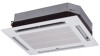
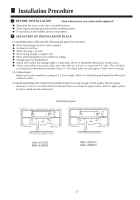
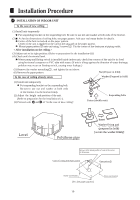
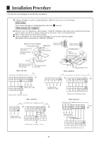
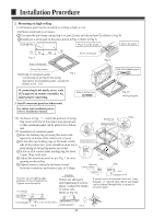
Installation Procedure 77. WIRING All supplied parts. materials and wiring operation must in appliance with local code and regulations.Use copper wire only. When make wiring, please refer to wiring diagram also.All wiring work must be done by qualified electricians. A circuit breaker must be installed, which can cut power supply to all system. Connecting of unit Remove cover of switch box (1) , drag wires into rubber tube A, then, after proper wiring with other wires, tighten clamp A. Connect wires of correct pole to the terminal block inside. Wind seal 12 around wires. (Be sure to do that, or, dew may occur). Upon connecting, replace control box cover (1) and (2). Moreover,connect the black terminal of indoor unit with the black terminal of outdoor unit properly using the connecting wire which has both white terminals in the accesory bag,and connect the blue terminal of indoor unit with the white terminal of out terminal as the same(For heat pump model).For cooling only unit,just connect the black terminalof indoor unit with the black terminal of outdoor unit properly. Terminal block Clip A Cover of control box(2) Grounding lead Rubber tube A Cover of control box(1) * Don't fail to seal it, or water may come in. Rubber tube Note: Have it sealed, leaving no space. Seal pad (small size 12 ) (Wind around wire) In Out Attach seal pad Field wiring Obscrve the following when connecting power supply terminal block: Connect wires of the Don't connect wires of Don't connect wires same specifications the same specifications of the different at two sides. at one side. specifications. Don't connect wires of different specifications to the same terminal block. (Loose wire may cause overheating of circuit) Connect wires of same specifications as shown in right Fig. 88. WIRING EXAMPLE As for outdoor unit circuit, please see Installation Manual of outdoor unit. Note: All electric wires have their own poles, poles must match that on terminal block. 99. INSTALLATION OF ORNAMENT PANEL Cautions for the installation Be sure to show customers Operation Manual and guide them how to operate unit correctly. Before installation. read also the Installation Manual of indoor unit. With this ornament , 2 or 3 air flow direction is not available. Suitable height is 3 m. Accessory Pad Pad 1. Prepare ornament panel Handling of ornament panel Ornament panel shall not be placed face down or against wall, neither on an uneven object. Don' t bend carelessly the swing flap, or, problem may occur. (1) Remove air inlet grill from ornament panel * 1 Push in the bar on inlet grill and lift it up. (Refer to Fig. 1) 2 Lift it up for about 45 degree and remove it from ornament. Tear off adhesive tape fixing air filter on the back of the air inlet grill. (Refer to Fig. 2) (2) Remove cover plate at corner Tear off the adhesive tape, and slide it off. (Refer to Fig. 3) 22 Bar Fig. 1 45 Adbesive tape Fig. 2 Slide Fig. 3
-
 1
1 -
2
-
3
-
4
-
5
-
6
-
7
-
8
-
9
-
10
-
11
-
12
-
13
-
14
-
15
-
16
-
17
-
18
-
 19
19 -
 20
20 -
 21
21 -
 22
22 -
 23
23 -
 24
24 -
 25
25 -
 26
26
 |
 |