Haier HSU-36LEA03 User Manual
Haier HSU-36LEA03 Manual
 |
View all Haier HSU-36LEA03 manuals
Add to My Manuals
Save this manual to your list of manuals |
Haier HSU-36LEA03 manual content summary:
- Haier HSU-36LEA03 | User Manual - Page 1
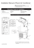
to the user according to this manual. Necessary Tools for Installation 1.Driver or soap-and-water solution 11.Measuring tape 12.Reamer Drawing for the installation of indoor and cap 4 7 Cover 1 8 Cushion 4 9 Pipe supporting plate 1 10 Drain-elbow 1 Arrangement of piping directions - Haier HSU-36LEA03 | User Manual - Page 2
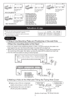
) HSU-36LEA03(T3) HSU-30LEA13(T3) Selection of pipe To this unit, both liquid and gas pipes shall be insulated as they become Iow temperature in operation. Use optional parts for piping set or pipes covered with equivalent insulation material. Liquid pipe ( ) Gas pipe ( ) For 18K 6.35mm(1/4") 12 - Haier HSU-36LEA03 | User Manual - Page 3
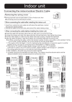
its service agent HSU-32LEA13-W HSU-36LEA03(T3) HSU-30LEA13(T3) Outdoor unit LN BR BL POWER SUPPLY Y/G 34 5 Power cable: 3G2.5mm 4G0.75mm 2 LN Indoor unit 1 { power plug HSU-24LEB03(T3) Outdoor unit 34 5 Power cable: 3G2.5mm 3G0.75mm 2 1 Indoor unit Outdoor unit HSU-18LEB03(T3) 12 - Haier HSU-36LEA03 | User Manual - Page 4
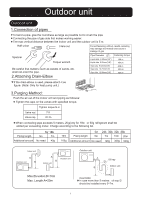
(3/8") 18N.m 40N.m Be careful that matters, such as wastes of sands, etc. shall not enter the pipe. 2.Attaching Drain-Elbow Gas side 9.52mm(3/8") Gas side 12.7mm(1/2") Gas side 15.88mm(5/8") 40N.m 50N.m 60N.m If the drain-elbow is used, please attach it as figure. (Note: Only for heat pump unit
-
 1
1 -
 2
2 -
 3
3 -
 4
4
 |
 |
No.0010518785
Installation Manual of Room Air Conditioner
Read this manual before installation
1.Driver
2.Hacksaw
3.Hole core drill
4.Spanner(17,19 and 26mm)
5.Torque wrench(17mm,22mm,26mm)
6.Pipe cutter
7.Flaring tool
8.Knife
9.Nipper
12.Reamer
10.Gas leakage detector or
soap-and-water solution
11.Measuring tape
Explain sufficiently the operating means to the user
according to this manual.
A
B
C
D
E
F
G
Optional parts for piping
Mark
Parts name
Non-adhesive tape
Adhesive tape
Saddle(L.S) with screws
Connecting electric cable
for indoor and outdoor
Drain hose
Heating insulating material
Piping hole cover
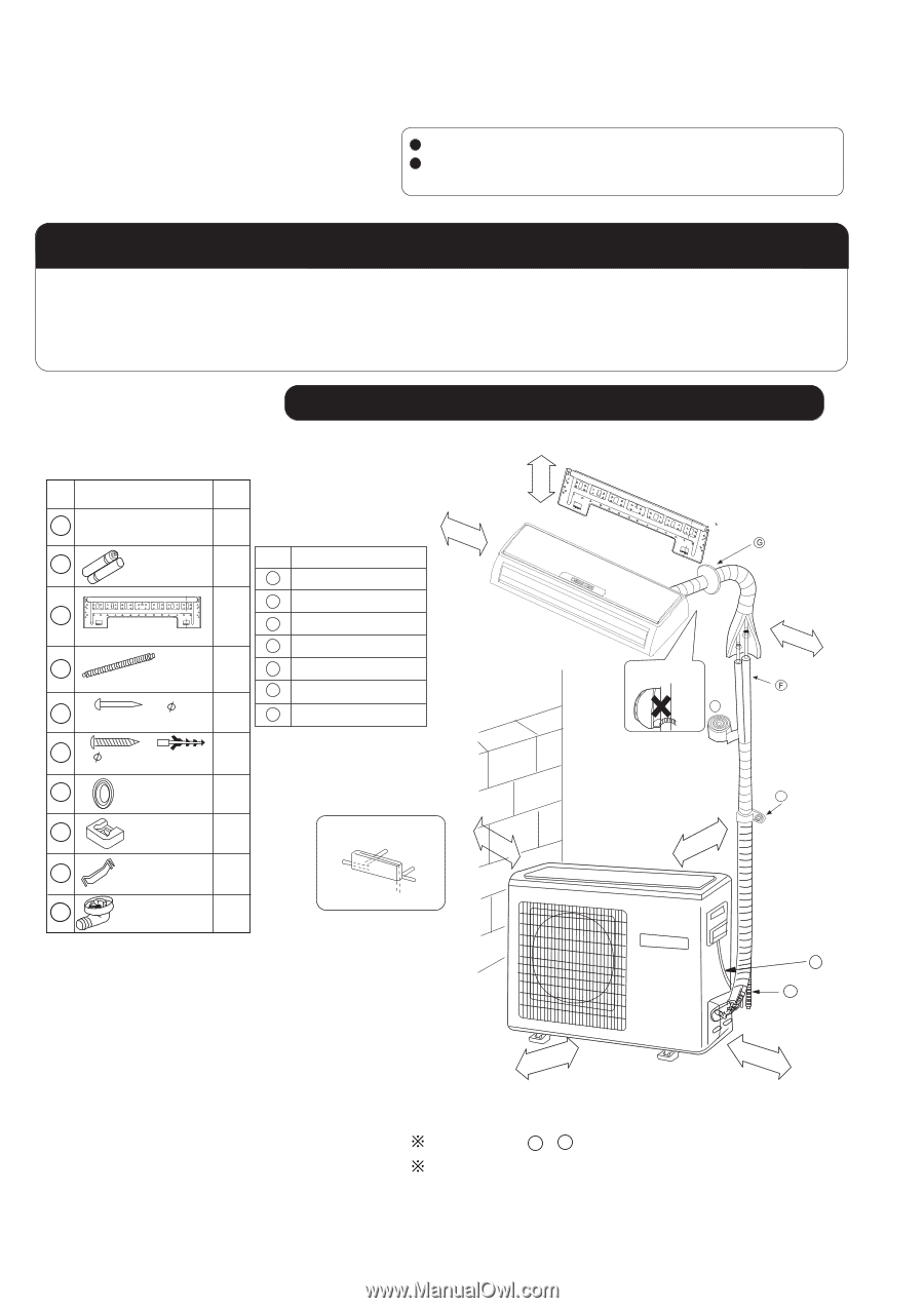
Arrangement of piping directions
Rear left
Rear
right
Left
Below
Right
No.
Accessory parts
Remote controller
R-03 dry battery
Mounting plate
Drain hose
Steel nail, cement
Screw
Plastic cap
Cover
Cushion
1
1
2
3
4
5
6
7
8
9
2
1
1
6
4
1
4
1
Number
of
articles
Accessory parts
4X50
4X25
Pipe supporting plate
Drawing for the installation of indoor and outdoor units
Necessary Tools for Installation
10
Drain-elbow
1
The marks from
to
in the figure are the parts numbers.
The distance between the indoor unit and the floor should be
more than 2m.
A
G
Attention must be paid to
the rising up of drain hose
m
c
5
n
a
h
t
e
r
o
m
m
c
0
1
n
a
h
t
e
r
o
m
m
c
0
1
n
a
h
t
e
r
o
m
A
C
m
c
0
1
n
a
h
t
e
r
o
m
m
c
0
6
n
a
h
t
e
r
o
m
m
c
5
1
n
a
h
t
e
r
o
m
m
c
0
1
n
a
h
t
e
r
o
m
D
E