Haier HSU18VHJ User Manual
Haier HSU18VHJ Manual
 |
View all Haier HSU18VHJ manuals
Add to My Manuals
Save this manual to your list of manuals |
Haier HSU18VHJ manual content summary:
- Haier HSU18VHJ | User Manual - Page 1
horizontally. ƽ When fitting the unit to wall surface, roof or rooftop, fix a supporter securely with nails or wires in consideration of earthquake and strong wind. ƽ If vibration may look different. Read this manual before installation. Explain the operation or the unit to the user according to this - Haier HSU18VHJ | User Manual - Page 2
for right piping Lid for under piping pipe Lid for left piping Heat insulation material Drain hose Indoor/outdoor electric cable Piping Pipe supporting plate Fix with adhesive tape ƽ Indoor/outdoor electric cable and drain hose must be bound with refrigerant piping with protecting tape. [ Other - Haier HSU18VHJ | User Manual - Page 3
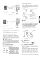
Outdoor unit A 1(N) 2 (L) 3(C) NDSV18-W Power cable: ^POWER 3G2.5mm 2 1. If the supply cord is damaged, it must be replaced by the manufacturer or its service agent or a similar qualified person. The type of connecting wire is H05RN-F or H07RN-F. 2. If the fuse on PC board is broken please change - Haier HSU18VHJ | User Manual - Page 4
valve 3-way valve 2-way valve 3-way valve Step 7. 2-way valve 3-way valve Service port cap Valve rod cap Valve rod cap CAUTION ƽ If the refrigerant of the Please kindly explain to our customers how to operate through the instruction manual. Check Items for Test Run Put check mark in boxes Gas - Haier HSU18VHJ | User Manual - Page 5
Manual de instalación de aparato de aire acondicionado Preparación Herramientas necesarias para realizar la como referencia. Puede que su aparato no coincida exactamente con ella. Lea este manual antes de la instalación Explique el uso del aparato al usuario siguiendo las instrucciones de este - Haier HSU18VHJ | User Manual - Page 6
Control remoto (1) Batería seca R-03 (2) Placa de montaje (1) Tapón de plástico (4) Tornillo ø4X25 (4) Accesorios Manguera de drenaje (1) Acolchado (4) Codo de drenaje (1) Placa de soporte del tubo (1) Selección de tubo Para 12K Para 18K Tubo de líquido (Ø) 6,35mm (1/4") 6,35mm (1/4") Tubo - Haier HSU18VHJ | User Manual - Page 7
Unidad interior 4G0.75mm2 NDSV12-W ALIMENTACIÓN Cable de alimentación: ı3G1.5mm2 1(N) 2 (L) 3(C) 1(N) 2 (L) 3(C) Unidad exterior Asegúrese de que no penetren residuos o suciedad en el tubo. La longitud estándar del tubo es de 5m. Si el tubo tiene más de 10m, se verán afectadas las funciones - Haier HSU18VHJ | User Manual - Page 8
Botella de refrigerante y colector de carga. Prueba de instalación y ejecución de la prueba Explique al cliente cómo utilizar el aparato utilizando el manual de instrucciones. Compruebe los siguientes puntos de prueba Escriba una marca en los cuadros ¿Existe una fuga de gas en la conexión del - Haier HSU18VHJ | User Manual - Page 9
érieure - Sélectionnez un emplacement qui soit ● Solide sans vibration et offrant un support suffisant. ● N'est pas affecté par de la chaleur ou de la unité doit être installée sur un mur, un toit ou la toiture, fixez un support avec des clous ou des fils en tenant compte des séismes et vents forts. ● - Haier HSU18VHJ | User Manual - Page 10
tuyauterie jusqu'à la marque du trou pour une tuyauterie arrière-gauche qui est marquée sur les matériaux d'isolation thermique. 10 Ecrou de blocage Support de conduit Faisceau de câbles de l'unité Effectuez les 6 entailles Remarque Lors de la connexion du câble, confirmez le numéro de la borne - Haier HSU18VHJ | User Manual - Page 11
Unité intérieure 4G0.75mm2 1(N) 2 (L) 3(C) Unité extérieure 1(N) 2 (L) 3(C) NDSV12-W ALIMENTATION Câble électrique : ı3G1.5mm2 Assurez-vous qu'aucune impureté ni débris ne sont entrés dans le tuyau. La longueur standard du tuyau est de 5 m. Au delà de 10 m, l'unité ne fonctionnera pas - Haier HSU18VHJ | User Manual - Page 12
5. Pas de fuite de gaz? En cas de fuite de gaz, resserrez les pièces de connexion du tuyau. Lorsque la fuite est maîtrisée, passez à l'étape 6 Si elle n'a pas été maîtrisée, videz le réfrigérant de l'orifice d'entretien. Après avoir effectué l'évasement et le vide, remplissez de réfrigérant indiqué
-
 1
1 -
 2
2 -
 3
3 -
 4
4 -
 5
5 -
 6
6 -
 7
7 -
8
-
9
-
10
-
11
-
12
 |
 |
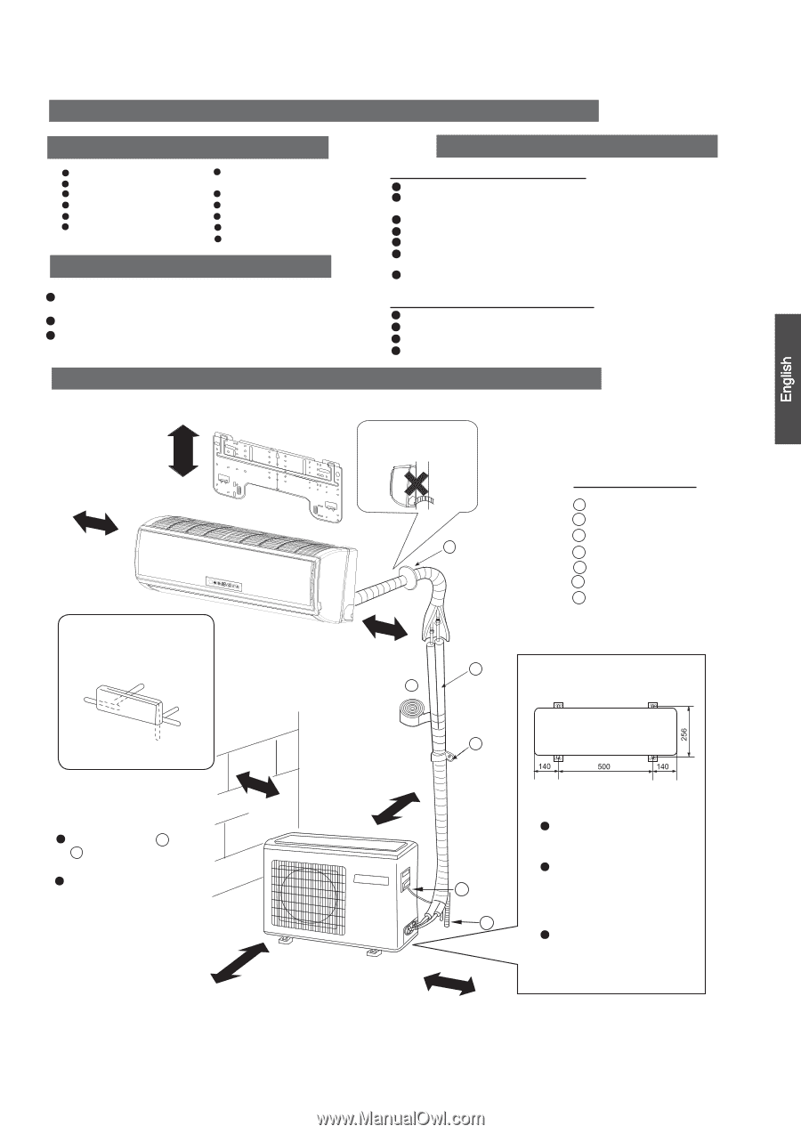
Drawing for the installation of indoor and outdoor units
Necessary Tools for Installation
Hammer
Torque wrench
(17mm,22mm,26mm)
Nipper
Reamer
Hacksaw
Pipe cutter
Gas leakage detector or
soap-and-water solution
Hole core drill
Flaring tool
Spanner(17,19 and 26mm)
Knife
Measuring tape
Place where the distance of more than lm from televisions, radios, wireless apparatuses
and fluorescent lamps can be left.
In the case of fixing the remote controller on a wall, place where the indoor unit can
receive signals when the fluorescent lamps in the room are lightened.
Place, where discharged wind and noise do not cause a nuisance to the neighbors.
Place, where a distance marked
±
is available as illustrated in the above figure.
Before inserting power plug into receptacle, check the voltage without fail.
The power source is the same as the corresponding name plate.
Install an exclusive branch circuit of the power.
A receptacle shall be set up in a distance where the power cable can be
reached.Do not extend the cable by cutting it.
Selection of Installation Place
Power
Source
Preparation
NO.0010532902
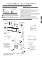
Installation Manual of Room Air Conditioner
F
A
C
E
D
Optional parts for piping
Non-adhesive tape
Adhesive tape
Saddle (L.S) with screws
Connecting electric cable
for indoor and outdoor
Drain hose
Heating insulating material
Piping hole cover
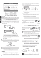
Floor fixing dimensions of the
outdoor unit (Unit:mm)
Fixing of outdoor unit
Fix the unit to concrete or block
with bolts (10mm) and nuts firmly
and horizontally.
When fitting the unit to wall
surface, roof or rooftop, fix
a supporter securely with nails
or wires in consideration of
earthquake and strong wind.
If vibration may affect the
house, fix the unit by attaching a
vibration-proof mat.
The marks from
to
in the figure are the
parts numbers.
The distance between
the indoor unit and the
floor should be more
than 2m.
The models adopt HCFC free refrigerant R410A
more than
10cm
more than 5cm
more than 10cm
more than 10cm
more than
10cm
more than15cm
more than 60cm
A
G
A
F
C
E
D
G
B
Arrangement of piping
directions
Rear left
Left
Rear
right
Right
Below
G
Attention must be paid to
the rising up of drain hose
The above picture is for your reference only. Your product may look different.
Read this manual before installation.
Explain the operation or the unit to the user according to this manual.
Indoor Unit - Select a plocation that is
Outdoor Unit - Select a plocation that is
Robust not causing vibration, where the body can be supported sufficiently.
Not affected by heat or steam generated in the vicinity, where inlet and outlet of the
unit are not disturbed.
Possible to drain easily, where piping can be connected with the outdoor unit.
Where cold air can be spread in a room evenly.
Nearby a power receptacle. (Refer to drawings).
Not less affected by rain or direct sunlight and is sufficiently ventilated.
Strong enough to bear the unit, where vibration and noise are not increased.