Harman Kardon AVR 140 Quick Start Guide - Page 3
Audio Connections - surround sound receiver
 |
View all Harman Kardon AVR 140 manuals
Add to My Manuals
Save this manual to your list of manuals |
Page 3 highlights
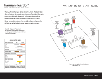
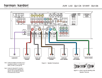
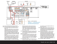
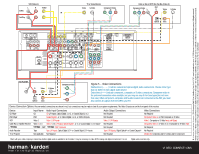
FM Antenna AM Antenna CD PLAYER L R Optical Coax The Bridge (100W, 1A MAX) (50W, 0.5A MAX) The BridgeTM 140 AUDIO RECORDER REC/IN PLAY/OUT Figure 4 - Audio Connections Dashed lines (- - - -) indicate coaxial and optical digital audio connections. Choose either type (but not both) for each digital audio source. Step 4. Connect AM and FM antennas (as shown above); see page 12. Step 5. Connect source components, as shown in Figures 4 and 5, and the Device Connection Options chart on the back of this Guide (see pages 12-13). AUDIO connections: Right channel (red) on source to right (red) on AVR, and left channel (white) on source to left (white) on AVR. DIGITAL AUDIO connections, if available: Choose either coax (orange) to coax (orange) OR optical to optical for each device. The Coax 1 input defaults to the DVD player, and the Optical 1 input defaults to Video 2 (Cable/Sat), but either may be reassigned. Assign the other digital inputs and outputs as appropriate for your equipment (see Step 7). VIDEO connections: Choose component (Y/Pb/Pr - green/blue/ red), composite (yellow) or S-video (4-pin) for each video source. Connect the Composite and S-Video Monitor outputs to your video monitor (TV). The Component Video 1 input defaults to any of the DVD, Tuner, CD or Tape sources. The Component Video 2 input defaults to any of the Video 1, 2 or 3 sources, or the 6-/8-channel direct inputs. However, either component video input may be reassigned using the Input Setup menu. Switch your TV set's input to match the type of video used for the currently selected source. TheBridgeTM : Make sure the AVR 140 is turned off, then connect the optional TheBridgeTM to the DMP connector. Dock your compatible iPod® (not included) in TheBridgeTM . Step 6. Plug all components into AC power outlets. The outlets on the back of the AVR 140 should be used only for low-current products, such as CD or DVD players, and the total should not exceed 100 watts. Basic Receiver Configuration Step 7. Select digital inputs: If your DVD is connected to Coax 1, and your cable or satellite TV box (Video 2 source) is connected to Optical 1, no adjustment is needed. For any other digital-device connections, use the on-screen Input Setup menu or the front-panel Digital Select button and the arrow buttons to select an optical or coaxial digital input (see pages 17 and 30). Step 8. Select a surround mode: Press the Surround Mode button on the front panel to select Dolby® Pro Logic® II - Movie. (You may select other modes later as you become familiar with the AVR 140; see pages 18-20 and 27-33.) Step 9. Configure speakers: No action is needed if you have five or six "small" satellite-type speakers and a subwoofer. Otherwise, use the OSD Manual Setup Menu, or press the Speaker button and then the Set and arrow buttons to select the correct speaker choices for your system (see pages 20-22). Step 10. Set output levels: Set the volume to -15dB. Sit in the listening position and press the Test button on the remote. The test tone (which sounds like static) will circulate from speaker to speaker. Press the up/down arrow keys to adjust the level of each speaker until they all sound the same. If you have an SPL meter, set it to 75dB on the C-Weighting, Slow scale. Press the Test button again to complete the process. In six-speaker systems, the levels for both surround back channels will be set using the single surround back speaker to optimize Logic 7® and other 7-channel processing (see pages 23-24). Step 11. Your system is configured - sit back and enjoy! SPEAKER AND AUDIO CONNECTIONS
-
 1
1 -
 2
2 -
 3
3 -
 4
4
 |
 |
