Harman Kardon AVR 140 Quick Start Guide - Page 4
Video Connections - parts
 |
View all Harman Kardon AVR 140 manuals
Add to My Manuals
Save this manual to your list of manuals |
Page 4 highlights
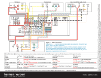
250 Crossways Park Drive, Woodbury, New York 11797 www.harmankardon.com © 2005 Harman International Industries, Incorporated. All rights reserved. Harman Kardon, Harman International, Power for the Digital Revolution and Logic 7 are registered trademarks, and The Bridge logo is a trademark, of Harman International Industries, Incorporated. iPod is a registered trademark of Apple Computer, Inc. Dolby and Pro Logic are registered trademarks of Dolby laboratories. Part No. CQE1A258Z VCR (Video 1) L R VIDEO In/Rec IN Out/Play TV or Video Monitor Video S-Video Component Video Y Pb Pr (The Bridge) (100W, 1A MAX) (50W, 0.5A MAX) Cable or Sat or HDTV Set-Top Box (Video 2) Component Video Y Pb Pr L OUT R Video S-Video Optical Coax 140 DVD PLAYER L R Video S-Video Optical Coax Component Video Y Pb Pr Figure 5 - Video Connections Dashed lines (- - - -) indicate coaxial and optical digital audio connections. Choose either type (but not both) for each digital audio source. Dotted lines indicate component, composite or S-video connections. Component video is the preferred connection when available, but you may use any of the three types (but not more than one). When component, composite and S-video sources are connected to the AVR, you must also connect all outputs from the AVR to your TV. Device Connection Options: Recommended connections are shown in red, but connections may be made to best fit your system requirements. The Video 3 inputs are on the front panel of the receiver. Device CD Player DVD Player VCR Cable Box or Satellite Receiver The BridgeTM Audio Recorder TV or Projector Input Name Audio Input Connections CD CD L/R Inputs, Optical Digital 1 or 2, or Coaxial Digital 1 or 2 DVD Coaxial Digital 1 or 2, Optical Digital 1 or 2, or DVD L/R Inputs Video 1 Video 1 L/R Inputs Video 2 or 3 Video 2 or 3 L/R Inputs, Optical Digital 1 or 2, or Coaxial Digital 1 or 2 Inputs* TheBridgeTM DMP TheBridgeTM DMP Connector Tape Tape L/R Inputs, Optical Digital 1/2** or Coaxial Digital 1/2** Inputs Not Applicable Not Required Audio Output Connections Not Required Not Required Video 1 L/R Outputs Not Required Not Required Tape L/R Outputs, Digital Optical** or Coaxial Outputs** Not Required Video Connections Not Required Component Video 1, or DVD Composite or S-Video Video 1 Composite or S-Video Input and Output Component Video 2, or Video 2 or 3 Composite or S-Video Input Not Required Not Required Monitor-Out Composite and/or S-Video and/or Component *Check with your cable company to determine whether digital audio is available for all channels. It may be necessary to make BOTH analog and digital connections if it is not. **Digital audio recorders only. ® Power for the Digital Revolution.® VIDEO CONNECTIONS
-
 1
1 -
 2
2 -
 3
3 -
 4
4
 |
 |
