Harman Kardon AVR 240 Quick Start Guide - Page 3
Bridge - cabling
 |
View all Harman Kardon AVR 240 manuals
Add to My Manuals
Save this manual to your list of manuals |
Page 3 highlights
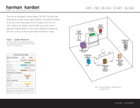
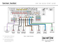
FM Antenna AM Antenna CD PLAYER L R Optical Coax The Bridge The BridgeTM Figure 5 - Connecting EzSet+ Microphone AUDIO RECORDER REC/IN PLAY/OUT Figure 4 - Audio Connections Dashed lines (- - - -) indicate coaxial and optical digital audio connections. Choose either type (but not both) for each digital audio source. Step 4. Connect AM and FM antennas as shown above (see page 15). Step 5. Connect source components, as shown in Figures 4 and 6 and the Device Connection Options chart on the back of this Guide (see pages 15-16). AUDIO connections: Right channel (red) on source to right (red) on AVR, and left channel (white) on source to left (white) on AVR. DIGITAL AUDIO connections, if available: Choose either coax (orange) to coax (orange) OR optical to optical for each device. The Coax 1 input defaults to the DVD player, and the Optical 1 input defaults to Video 2 (Cable/Sat), but either may be reassigned. Assign the other digital inputs and outputs as appropriate for your equipment (see Step 7). VIDEO connections: Choose component (Y/Pb/Pr - green/blue/ red), composite (yellow) or S-video (4-pin) for each video source. Connect the Composite and S-Video Monitor outputs to your video monitor (TV). The Component Video 1 input defaults to any of the DVD, Tuner, CD or Tape sources. The Component Video 2 input defaults to any of the Video 1, 2, 3 or 4 sources, or the 6-/8-channel direct inputs. However, either component video input may be reassigned using the Input Setup menu. Switch your TV set's input to match the type of video used for the currently selected source. TheBridgeTM : Make sure the AVR 240 is turned off, then connect the optional TheBridgeTM to the DMP connector. Dock your compatible iPod® (not included) in TheBridgeTM . Step 6. Plug all components into AC power outlets. The outlets on the back of the AVR 240 should be used only for low-current products, such as CD or DVD players, and the total should not exceed 100 watts. Basic Receiver Configuration Step 7. Select digital inputs: If your DVD is connected to Coax 1, and your cable or satellite TV box (Video 2 source) is connected to Optical 1, no adjustment is needed. For any other digital-device connections, use the On-Screen Input Setup menu, or the front-panel Digital Select and arrow buttons to select digital input (see pages 21, 36). Step 8. Select a surround mode: Press the Surround Mode button on the front panel to select Dolby® Pro Logic® II - Movie. (You may select other modes later as you become familiar with the AVR 240; see pages 22-24 and 33-39.) Step 9. Use + to configure and optimize your system: Plug the EzSet+ microphone into the front-panel Headphones Jack (Figure 5). Place the microphone at the center of the room, or at your normal listening position. If desired, the microphone may be attached to a standard camera tripod using the threads on the bottom of the microphone. Activate EzSet+ using the on-screen menu system (see pages 24-26). As EzSet+ senses the output of each speaker, you will hear loud test signals. When the on-screen menu indicates that setup is complete, your system is adjusted for output levels, delay times and speaker settings. Unplug the microphone and store it for future use. Step 10. Your system is configured - sit back and enjoy! SPEAKER AND AUDIO CONNECTIONS
-
 1
1 -
 2
2 -
 3
3 -
 4
4
 |
 |
