Harman Kardon BDS 800 Owners Manual - Page 17
Connecting Audio Sources, Connecting to a Local Area Network LAN, Connecting the AC Power
 |
View all Harman Kardon BDS 800 manuals
Add to My Manuals
Save this manual to your list of manuals |
Page 17 highlights
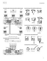
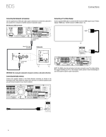
BDS Connections Connecting Audio Sources TV To Optical Output -OR- To Audio Output Connecting to a Local Area Network (LAN) Use a CAT. 5/RJ45 network cable (not supplied) to connect the BDS receiver's BD-Live connector directly to a network router, a network switch, a network modem or an Ethernet network wall jack that has Internet access. NOTE: The BDS receiver can not access content on other networked devices. The Network connection enables only the receiver's BD-Live features. See BD-Live Interactivity, on page 25, for details. To Internet Cat. 5/5E Network Modem Tape Deck Cable/Satellite Tuner To Optical Output Digital Audio Source To Play Output To Coaxial Output Connecting the AC Power The BDS receiver comes with a detachable AC power cord. This type of cord makes it easier for you to install and connect all other system wiring to the receiver's rear panel. The subwoofer has a non-detachable power cord. NOTES: s The power requirement for the BDS receiver is 110V - 240V AC, 50/60Hz, 110W (BDS 5 receiver) or 70W (BDS 2 receiver). The power requirement for the subwoofer is 110V - 120V AC, 60Hz, 200W (USA) or 220V - 240V AC, 50/60Hz, 200W (EU). Connecting to a power source other than the ones listed may damage the receiver or subwoofer, or cause abnormal operation. s Before connecting the AC power cords to wall outlets, confirm that you have correctly made all of the speaker connections, video connections and audio- component connections. Connect the female end of the receiver's detachable power cord to the receiver's AC Power Input connector. Plug the other end into a working, unswitched AC outlet. Plug the subwoofer's power cord into a working, unswitched AC outlet as well. Receiver Subwoofer Analog Audio Inputs 1 and 2: If you have an audio-only analog source component (such as a tape deck), connect its left and right analog outputs to the Analog Audio Input 1 or Analog Audio Input 2 jacks as shown in the illustration. NOTE: To hear a TV show through your BDS system, you need to connect the audio output of your TV to the BDS receiver. If your TV has a digital-audio output, you can connect it to one of the BDS receiver's digital inputs (see below). If your TV does not have a digital-audio output, you will need to connect the TV's analog-audio output to the BDS receiver's Analog Audio Input 1 or Analog Audio Input 2 jacks. Coaxial In and Optical 1/Optical 2 In: If you have an audio-only digital source component (such as a CD changer or video game), you can connect it to one of these inputs, as shown in the illustration. When using the Optical 1 and Optical 2 digital connections, gently push the cable connector through the panel connector's built-in shutter until it is firmly seated in the connector. NOTE: Use only one type of digital connection for each source component. PL0004-01001 110V - 240V, 50Hz/60Hz USA: 120V, 60Hz EU: 220V - 230V, 50Hz/60Hz Set the receiver's and subwoofer's Main Power switches in the "On" position. The receiver's Power indicator will turn amber, indicating that the receiver is in the Standby mode. s The subwoofer's LED will not light up until it receives a turn-on signal. See Subwoofer Controls and Connections, on page 7, for details. 17
-
 1
1 -
2
-
3
-
4
-
5
-
6
-
7
-
8
-
9
-
10
-
11
-
 12
12 -
 13
13 -
 14
14 -
 15
15 -
 16
16 -
 17
17 -
 18
18 -
 19
19 -
 20
20 -
 21
21 -
 22
22 -
23
-
24
-
25
-
26
-
27
-
28
-
29
-
30
-
31
-
32
-
33
-
34
-
35
-
36
-
37
 |
 |
