Harman Kardon MS 150 Owners Manual - Page 5
Rear-Panel Connections - speaker system
 |
View all Harman Kardon MS 150 manuals
Add to My Manuals
Save this manual to your list of manuals |
Page 5 highlights
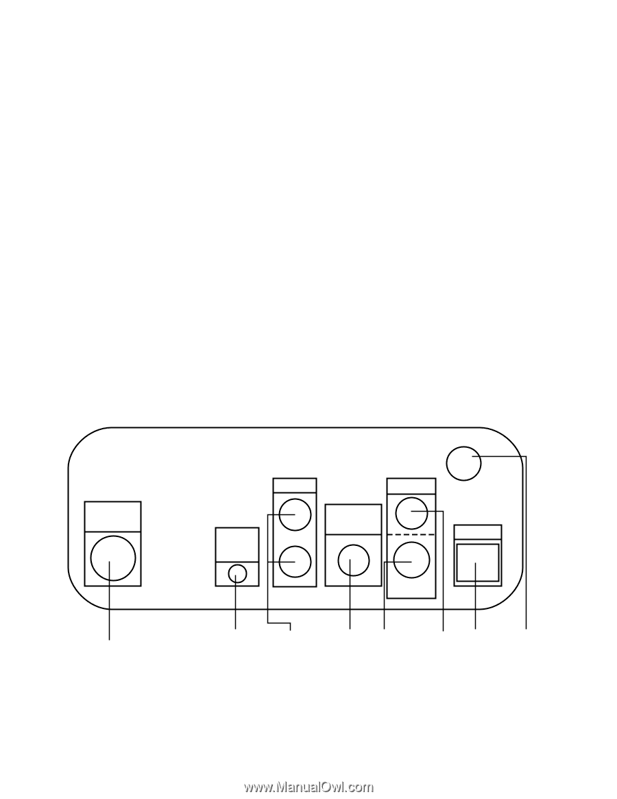
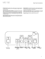
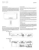
MS 150 Rear-Panel Connections DC Power Input: After making all other connections, plug in the power supply. Plug the included region-specific power cord into the included power supply and into an unswitched wall outlet. Analog/Optical-Digital Auxiliary Audio Input 1: Connect either the stereo mini plug cable or the optical-digital audio cable (both cables included) here, and connect the other end of the cable to a source device such as a portable CD player. Connect the stereo mini plug cable only to the player's line-level analog audio output or headphone jack, and connect the optical cable only to an optical-digital audio output. Select the Analog 1 or Digital Audio source. Auxiliary Analog Audio Input 3: Connect one end of a stereo RCA-type interconnect cable (not included) here, and connect the other end to the analog-audio outputs on a source device such as a tape deck. Subwoofer Output: Connect this full-range output to a powered subwoofer (not included) equipped with a low-pass filter for improved low-frequency (bass) reproduction, or connect it to an external amplifier or powered speakers. Composite and S-Video Outputs: Connect either of these outputs to a TV or video display for viewing videos or photos stored on a compatible iPod/iPhone that supports video browsing. No other displays are available through these outputs. FM Antenna Terminal: Connect the included FM antenna wire here. DC IN 24V 4.9A 5V 1A 122.6W DC Power Input DC Power Input ANALOG IN OPTICAL AUX IN ANTENNA FM75 Ω VIDEO OUT LFE/ SUBWOOFER i-TUNES S-VIDEO ANALOG/OPTICAL AUXILIARY ANALOG SUBWOOFER S-VIDEO DIGITAALnaAlUogX/IOLIpAtiRcYal- AUDIAOUIXNLPiUnTe-In 3 OUTPSUuTbwooferOUTPSU-TVideo AUDIO INPDUiTgital AUX Line-In 1 Output Output VIDEO USB OUTPUT FM ANTENNA OUTPUCTom(ipToUsNitEeS TERMINFAML Antenna VideoOONuLtYp)ut Terminal 5
-
 1
1 -
 2
2 -
 3
3 -
 4
4 -
 5
5 -
 6
6 -
 7
7 -
 8
8 -
 9
9 -
 10
10 -
 11
11 -
12
 |
 |