Harman Kardon RHK670 Owners Manual - Page 6
Harman Kardon RHK670 Manual
 |
View all Harman Kardon RHK670 manuals
Add to My Manuals
Save this manual to your list of manuals |
Page 6 highlights
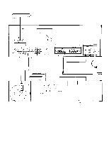
CONNECTIONS Repeat the procedure for the left speaker, taking care to observe the coding For the moment, leave the power cord (1) of of the conductors as described for the right the hk670 unconnected. Put the unit on the speaker. If the code is followed as shelf or table where it will be installed. Leave described, your speakers will be connected enough working space so you can make "in phase", which is important for solid bass connections easily. and precise lateral location of the sound All receivers require adequate ventila- source. To connect a second pair of speak- tion. The hk670 should not be installed on a ers, repeat the procedure for the right and cushion or rug, and a minimum of two left speakers of the second pair, using the inches' clearance should be provided above receiver terminals marked SYSTEM 2 (3). and behind. Connecting AM Antennas Connecting Speakers The ferrite loopstick AM antenna (4) on the Use two-conductor stranded wire to connect rear of the hk670 can be rotated to improve your speakers to the receiver. Eighteen gauge the reception of distant stations. AM recep- lamp cord (zip cord) is satisfactory, but a tion over extremely long distances can be heavier gauge (16 or 14 gauge) is preferable, obtained with an external "long wire" especially for distances over 25 feet. antenna, which can be connected to the AM Cut two segments of wire long enough ANTENNA terminal (5). to reach each speaker. Separate the conduc- tors at each end of the wire segments for a Connecting FM Antennas length of two or three inches. Then carefully A T-shaped (dipole) FM antenna is supplied remove about one-quarter inch of insulation with the receiver. However, reception will be from each free end. Twist the strands of each greatly improved if the receiver is connected conductor so they are smooth and tight with to an outdoor FM antenna system. If you live no loose strands. in a fringe reception area, or if your house is Lamp cord usually provides a "code" situated among obstructions (such as moun- that differentiates the two conductors. A con- tains or tall buildings), you may need a pow- ductor may be coded by a rib, sharp corner, erful, directional FM antenna. or indentations molded along the length of If no outdoor antenna is available, con- the insulation. In some cases, a thin colored thread is molded inside the insulation of one nect the lugs of the dipole (supplied with the unit) to the FM 30052, BAL terminals (6). The conductor. In others, one conductor is darker dipole can then be tacked or taped to a wall than the other, or the insulation of each con- or the back of a shelf. ductor is of a different color. Connect the bare ends of one segment Connecting Your Turntable of lamp cord to your right speaker as follows: The PHONO inputs (7) have been designed Connect the coded conductor to the to operate with a high-quality magnetic speaker's positive ("+") terminal, and the uncoded conductor to negative ("-"). (The phono cartridge. Do not use a ceramic phono cartridge. Turntables are supplied with "+" and "-" markings are in general use, their own signal cables. Consult the turntable although some speakers use other labeling owner's manual and determine which cable systems, such as "1" and "2","A" and "B", is for the left channel and which for the right. and so on.) Find the appropriate row of speaker Insert the plugs of the signal cables into the jacks on the receiver marked PHONO, LEFT connectors on the receiver marked SYSTEM 1 and RIGHT. If the turntable has a separate (2). Push in on the red plastic head of the ground wire, connect it to the knurled lug on connector marked RIGHT to reveal an open- the receiver marked GND (8). ing beneath. Insert the bare end of the coded conductor into the opening. Release the con- nector. The conductor should now be locked firmly into place. Insert the uncoded con- ductor into the adjacent black connector marked GND.
-
 1
1 -
 2
2 -
 3
3 -
 4
4 -
 5
5 -
 6
6 -
 7
7 -
 8
8 -
 9
9
 |
 |
