Harman Kardon RHK670 Owners Manual - Page 7
Harman Kardon RHK670 Manual
 |
View all Harman Kardon RHK670 manuals
Add to My Manuals
Save this manual to your list of manuals |
Page 7 highlights
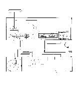
Tape Deck Connections To connect a tape deck, first connect the line outputs of the tape deck to the left and right TAPE 1 IN jacks (9) of the receiver. Then connect the left and right TAPE 1 OUT jacks (10) of the hk670 to the line inputs of the tape deck. To connect a second tape deck, repeat the procedure using the TAPE 2 IN and TAPE 2 OUT jacks (11) of the hk670. A standard DIN socket (12) is provided for tape decks equipped with a DIN connector. Time Delay and Signal Processing In addition to providing connections for tape decks, the TAPE IN and OUT jacks of the hk670 can be used to connect signal processors such as equalizers, noise reduction units, and dynamic range enhancers. In particular, the TAPE 2 OUT jacks can be used to connect a time delay system. In this configuration, the TAPE 2 OUT jacks provide the input for a time delay unit, which is then connected to separate amplifiers and speakers. Auxiliary Input Connection The AUX inputs (13) provide for an auxiliary source and -if desired playback with an additional cassette, cartridge, or open-reel tape deck. A special tuner for long wave, marine, aircraft, citizen's band, or the audio output of a television set are among the components that can also be connected to 1 the AUX inputs. AC Convenience Outlets The AC outlets on the rear panel provide connections for a turntable, tape deck, or other equipment drawing as much as 200 watts of current. One outlet is marked SWITCHED (14) and is "live" only when the receiver is switched on. The other, marked UNSWITCHED (15), provides power whenever the receiver itself is connected to a "live" AC outlet. Automatic turntables and changers should be plugged into the UNSWITCHED outlet to allow the automatic function to complete its cycle, even after the receiver has been turned off. Power Connection If you have completed all the connections you wish to make, you are now ready to place the receiver in its permanent position and plug its power line cord (1) into an AC outlet. OPERATION Power The POWER switch (16) is located on the left side of the front panel, and is "on" in the depressed position. Speaker Selection and Headphones The SPEAKER 1 (17) and SPEAKER 2 (18) switches select the pair of speakers to be played. When either switch is depressed, the corresponding pair of speakers is activated. The front panel HEADPHONES jack (19) accepts headphone for personal listening. Headphones may be used simultaneously with speakers if desired. Selecting Function Use the FUNCTION control (20) to select the desired program source. To Play Records Set the FUNCTION control (20) to PHONO, activate your turntable, and advance the VOLUME control (21) clockwise to a comfortable level. If you hear hum at average listening levels, turn the POWER switch (16) off and check to see that PHONO (7) and GND (8) connections are secure. Tone Controls To increase the loudness, turn the VOLUME control clockwise. The BALANCE control (22) shifts the sound to one speaker or the other. The BASS and TREBLE controls affect the frequency balance of the program material. Their neutral positions are at 12 o'clock. Turning the TREBLE control (23) clocwise increases the high frequencies. The BASS control (24) has the same effect on the low frequencies. When the LOUDNESS switch (25) is depressed, very high and very low frequencies are boosted at low settings of the VOLUME control. This compensates for the ear's relative insensitivity to extreme frequencies at low volume levels. The switch has little effect at VOLUME settings beyond 12 o'clock. When the MONO switch (26) is depressed, the audio signals from left and right channels are combined, and this monophonic signal is supplied to both speakers.
-
 1
1 -
 2
2 -
 3
3 -
 4
4 -
 5
5 -
 6
6 -
 7
7 -
 8
8 -
 9
9
 |
 |
