Hayward Aqua Plus Model: PL-PLUS-16V Installation - Page 15
Electrical Wiring - check cell
 |
View all Hayward Aqua Plus manuals
Add to My Manuals
Save this manual to your list of manuals |
Page 15 highlights
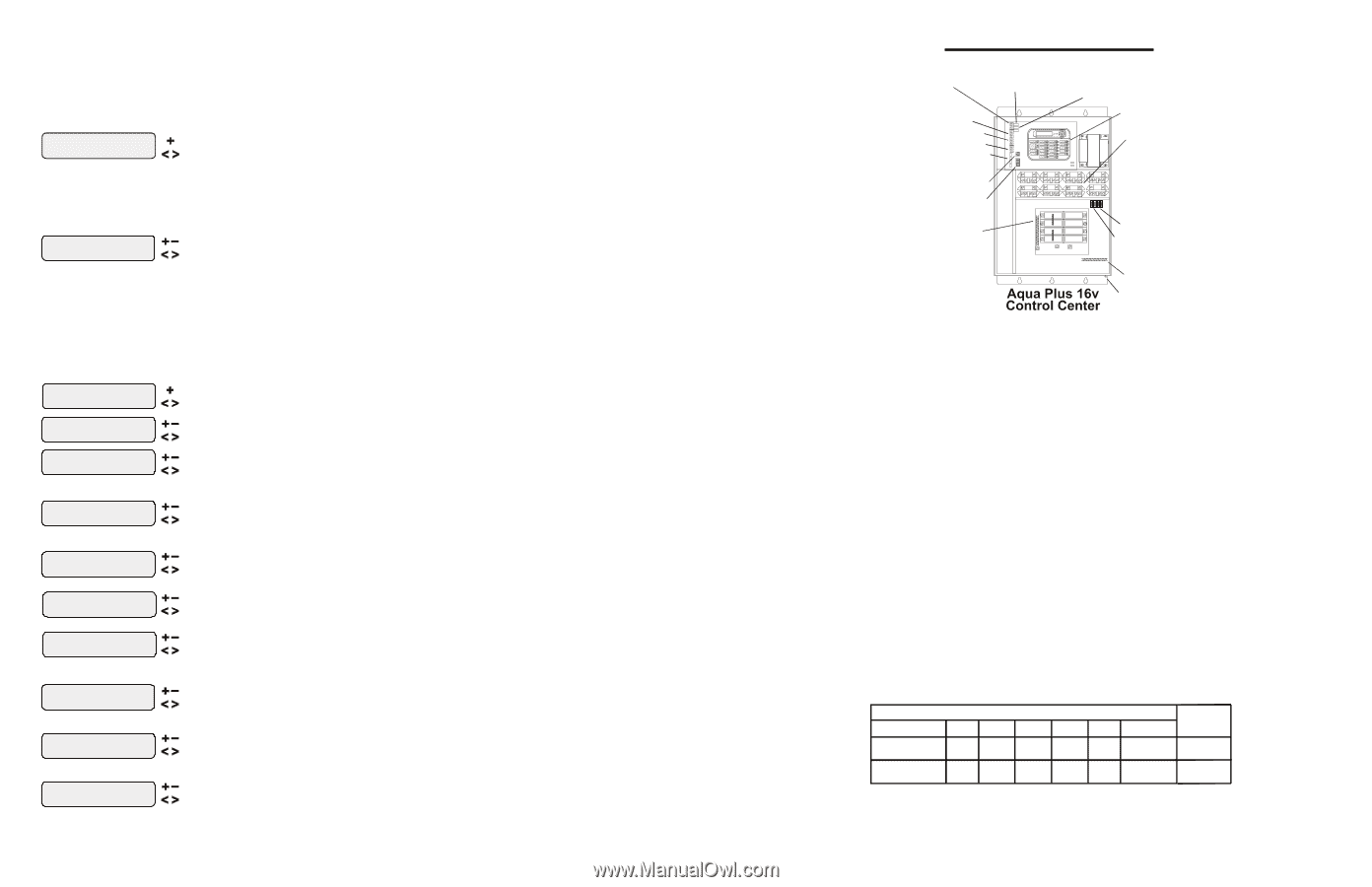
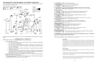
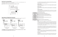
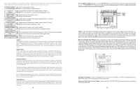
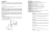
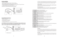
Allow Low Speed This menu only appears if the pool filter is configured for 2-speed operation. During default operation, high speed mode is used whenever the solar heater is on. If Allow Low Speed is enabled, low speed pump operation will be allowed during solar heating except for the first 3 minutes after solar heat turns on. only if optional ColorLogic Network Module is detected at power up ColorLogic Config. Push to activate ColorLogic options + to view/change Move to previous/next configuration menu ColorLogic Config. This menu appears if the optional ColorLogic Network Module is installed and detected at power up. Refer to the AQL-COLOR-MODHV manual for detailed installation and operation instructions. External Input Active Closed Toggle between Open and Closed (default) Move to next menu item or previous/next configuration menu External Input The external input device can either be normally open or normally closed. In this menu, select the state of the external input device when active. For example, if the switch is normally open and closes when active, set External Input to "Active Closed". NOTE: If an AQL-COLOR-MODHV ColorLogic Network Module is detected at startup, only the Lights Name menu will appear under Lights Configuration. Refer to the AQL-COLOR-MODHV manual for more information. Lights Config. + to view/change Push to access Lights options Move to previous/next configuration menu Lights Name Pool Light Rotates between all available names Move to next menu item or previous/next configuration menu Lights Function Manual On/Off for manual on/off, countdown timer and timeclock functions Lights Relay Standard Rotates between Manual On/Off (default), Countdown Timer, Low Speed- Filter, Timeclock, Solar, Low Speed-Spa Filter, Group, Super Chlorinate, and pH Dispense Move to next menu item Toggle between Standard (default), Dimmer and VSP Move to next menu item or previous/next configuration menu for all functions except solar, dimmer relay, super chlorinate pH dispense, low speed, and group Lights Interlock Toggle between Enabled and Disabled (default) Lights Interlock Disable Move to next menu item for group function only Lights Group Timer: None(Manual) Rotates between Manual On/Off (default),Countdown Timer and Timeclock Move to next menu item for group function only Lights Group Filter: Unaffected Options available depend on the function that is selected Move to previous/next menu item or next configuration menu for all functions except solar, dimmer relay, super chlorinate pH dispense, low speed, and group Lights Ext Input Toggle between Enabled and Disabled (default) Disabled Move to previous/next configuration menu for all functions except dimmer relay, super chlorinate pH dispense, low speed, and group Lights Freeze Toggle between Enabled and Disabled (default) Lights Freeze Disable Move to previous/next configuration menu if filter pump is set to variable speed and the relay type is set to standard Lights Pump Spd Select Settings Menu (default) or desired pump speed (Filter Lowest to Highest) Settings Menu Move to previous/next configuration menu 31 4. Electrical Wiring Remote Display/Keypad Connector Wireless Base Receiver Connector 4 Temp Sensor Inputs External Input Interlock 2 Heater Outputs 4 Valve Connectors AQL-CHEM Connector "Local" Display 8 High Voltage Relays Flow Switch Connector Cell Connector Subpanel N L2 L1 Control Power Input pH Dispense Output Ground Bus Bar Bonding Lug(s) The Aqua Plus 16v Control Center. Low voltage connections will be made to actuators, sensors, remote keypad, etc. High voltage connections will be made to pumps, lights, etc., as well as providing direct input power to the Control Center. Always: -Ensure that Power is disconnected prior to doing any wiring -Follow all local and NEC (CEC if applicable) codes -Use copper conductors only Main Service (Power to the Circuit Breaker Subpanel) The Aqua Plus 16v circuit breaker subpanel is rated for 100A service. Run properly rated conductors (L1, L2, N, and ground) from the primary house electrical panel to the main power connections on the Aqua Plus 16v circuit breaker base. The connection at the main house panel should be to a 240VAC circuit breaker rated at 100A maximum. Grounding and Bonding Connect a ground wire from the primary electrical panel to the Aqua Plus 16v ground bus bar. Also ground each piece of high voltage (120 or 240VAC) equipment that is connected to the Aqua Plus 16v control relays or circuit breakers. The Aqua Plus 16v should also be connected to the pool bonding system by an 8AWG (6AWG for Canada) wire. A lug for bonding (2 for Canada) is provided on the outside/bottom of the Aqua Plus 16v enclosure. Circuit Breaker Installation and Wiring Circuit breakers are to be supplied by the installer. See the chart below for a list of suitable circuit breakers that can be used. Follow the code and the circuit breaker manufacturer's rating requirements regarding the size and temperature rating for wiring. Note that some pool equipment may be required to be connected to ground fault circuit breakers-check local and NEC (CEC) codes. Manufacturer Siemens SUITABLE LISTED BREAKERS Tightening Single Double Twin Quad GFCB Filler Plates Torque QP QP QT QT QPF QF3 25lb-in Murray MP-T MP-T MH-T MH-T MP-GT LX100FP 25lb-in General Purpose Outlet If desired, a duplex receptacle with weatherproof cover (supplied by installer) may be installed in the knockouts on the lower right side of the Aqua Plus 16v enclosure. Per code, the receptacle should be a GFCI type. Alternatively, connect a standard receptacle to a GFCB. 12
-
 1
1 -
2
-
3
-
4
-
5
-
6
-
7
-
8
-
9
-
 10
10 -
 11
11 -
 12
12 -
 13
13 -
 14
14 -
 15
15 -
 16
16 -
 17
17 -
 18
18 -
 19
19 -
 20
20 -
21
-
22
-
23
-
24
 |
 |