Hayward HeatPro® Heat Pro Installation - Page 10
Plumbing Specifications and Layout, NOTICE - heater parts
 |
View all Hayward HeatPro® manuals
Add to My Manuals
Save this manual to your list of manuals |
Page 10 highlights
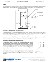
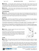
Page 10 of 20 HEATPRO HEAT PUMP HP13023770 Rev: E Plumbing Specifications and Layout The figure below illustrates the standard plumbing layout with a single heat pump unit. POOL PUMP FILTER POOL HEATER MANUAL ISOLATION VALVES CHECK VALVE CHEMICAL LOOP CHEMICAL FEEDER FROM POOL OR SPA MANUAL BYPASS VALVE TO POOL OR SPA NOTICE -The heat pump must be protected from back siphoning of water. If there is any chance of back siphoning, provide a check valve between the pool and the filter pump inlet. Failure to follow the instructions may result in property damage due to flooding. NOTICE -Automatic erosion type chlorinators, if used, must be installed downstream (between the heat pump and the pool) of the heat pump, and a check valve (or Hartford Loop) installed in a manner that will not allow the raw chlorine to drain back to the heat pump when the water pump is off. Failure to follow the instructions may result in property damage. NOTICE - Do not pour chemicals directly into the skimmer. It could result in damage to your system and heat pump. Arrangement of pool system components other than as illustrated previously and in the following diagrams can affect the operation of the heat pump's water pressure switch. Location of the heat pump above or below the elevation of the pool water surface can also affect operation of the switch. In general, the pressure switch can be adjusted to accommodate this effect if the heat pump water connections are no more than six (6) feet [1,8 m] below the pool water surface or no more than fifteen (15) feet [4,6 m] above it. See instructions for pressure switch adjustment in the heat pump start up section of this manual. If the heat pump is installed outside of this range, an external pressure switch may need to be installed in the plumbing upstream of the heat pump. For more information call Hayward Technical Service at 908 355-7995. Be advised, that when pool equipment is located below the pool surface, a leak can result in large-scale water loss or flooding. Hayward is not responsible for water loss, flooding or damage caused by either occurrence. USE ONLY HAYWARD GENUINE REPLACEMENT PARTS Pomona, CA Clemmons, NC Nashville, TN Tel: 908.351.5400 www.haywardpool.com
-
 1
1 -
2
-
3
-
4
-
 5
5 -
 6
6 -
 7
7 -
 8
8 -
 9
9 -
 10
10 -
 11
11 -
 12
12 -
 13
13 -
 14
14 -
 15
15 -
16
-
17
-
18
-
19
-
20
-
21
 |
 |
