Hayward Max-Flo II All Max-Flo II models - Page 10
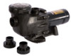
Use Only Hayward Genuine Replacement Parts, Max-flo Ii - pump diagram
 |
View all Hayward Max-Flo II manuals
Add to My Manuals
Save this manual to your list of manuals |
Page 10 highlights
Max-Flo II ™ Series Page 10 of 16 10. Gently wipe the black, polished surface of the spring seal assembly with a clean, soft, cotton cloth. 11. Press the spring seal assembly (item #12) onto the motor shaft - black polished surface facing toward the polished surface of the ceramic seat. Replacing the Impeller and Diffuser (See Parts Diagram on page 11 of this manual for pump component locations.) 11. Screw the impeller (item#10) onto the motor shaft in a clockwise direction. Tighten snugly by holding motor shaft with wrench as noted in step #4. 12. Place the diffuser (item #9) over the impeller (item#10) onto the seal plate (item#13), aligning the three (3) protruding pins with the matching holes in the seal plate (item#13). Note: Arrow on diffuser (item #9) will face up. Replace two diffuser screws (item #7). Replacing the Motor Assembly (See Parts Diagram on page 11 of this manual for pump component locations.) 14. Re-attach motor end cover/canopy by using the two (2) hex shaped screws. Slide the motor assembly with the diffuser (item#9) in place, into pump/strainer housing (item#4), being careful not to disturb the diffuser gasket (item#8). 15. Re-attach assembly to pump/strainer housing (item#4) using the four (4) 5/16"" x 1 3/4" hex head bolts. (Be sure housing gasket (item#11) is in place, and lubricated. Replace if damaged). Tighten alternately and evenly to 185 in-lbs using torque pattern in diagram 1 at bottom of this page. Diagram 1 www.haywardpool.com USE ONLY HAYWARD GENUINE REPLACEMENT PARTS
-
 1
1 -
2
-
3
-
4
-
 5
5 -
 6
6 -
 7
7 -
 8
8 -
 9
9 -
 10
10 -
 11
11 -
 12
12 -
 13
13 -
 14
14 -
 15
15 -
16
 |
 |
