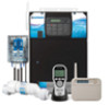
Hayward Pro Logic® Models: PL-PS-4 PL-PS-8 PL-PS-16 PL-PS-16V Installatio
Hayward Pro Logic® Manual
 |
View all Hayward Pro Logic® manuals
Add to My Manuals
Save this manual to your list of manuals |
Hayward Pro Logic® manual content summary:
- Hayward Pro Logic® | Models: PL-PS-4 PL-PS-8 PL-PS-16 PL-PS-16V Installatio - Page 1
Pro Logic Automation and Chlorination Installation Manual for models PL-PS-4 PL-PS-8 PL-PS-16 PL-PS-8-V PL-PS-16-V www.haywardnet.com - Hayward Pro Logic® | Models: PL-PS-4 PL-PS-8 PL-PS-16 PL-PS-16V Installatio - Page 2
FOLLOW ALL INSTRUCTIONS • ! WARNING: Disconnect all AC power during installation. • connect the local common bonding grid in the area of the swimming pool, spa, or hot tub to these terminals with an insulated or bare copper conductor not smaller than 8 AWG US / 6 AWG Canada. • All field installed - Hayward Pro Logic® | Models: PL-PS-4 PL-PS-8 PL-PS-16 PL-PS-16V Installatio - Page 3
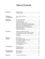
10 Turbo Cell 11 Flow Switch 11 Main Service 12 Grounding and Bonding 12 Circuit Breaker Installation and Wiring 12 General Purpose Outlet 12 Pro Logic Control Power 13 High Voltage Pool Equipment 13 Low Voltage Wiring 15 Group Function 22 Configuration Menus 24 Maintenance Menu 40 - Hayward Pro Logic® | Models: PL-PS-4 PL-PS-8 PL-PS-16 PL-PS-16V Installatio - Page 4
need to complete an installation include: Circuit breakers None are included with control-see page 12 and inside of door for suitable breakers Wire 4-conductor cable (electronics unit to remote display/keypad) Wire/conduit for 100A service from main panel to Pro Logic Wire/conduit for filter pump - Hayward Pro Logic® | Models: PL-PS-4 PL-PS-8 PL-PS-16 PL-PS-16V Installatio - Page 5
Turbo Cell Flow Switch 4. Electrical Wiring (page 12) Main service Grounding and bonding Circuit breakers Pro Logic control power High Voltage pool equipment Low voltage wiring (temperature sensors, flow switch, etc.) 5. Pro Logic control configuration (program desired control operation) (page - Hayward Pro Logic® | Models: PL-PS-4 PL-PS-8 PL-PS-16 PL-PS-16V Installatio - Page 6
using the chlorinator features on the Pro Logic Control. If you are NOT using the chlorinator, it is recommended that you follow all of the other chemistry recommendations besides salt. Refer to the description of the Pro Logic configuration menu for information on enabling/disabling the chlorinator - Hayward Pro Logic® | Models: PL-PS-4 PL-PS-8 PL-PS-16 PL-PS-16V Installatio - Page 7
/gallons and meters/liters) if pool size is unknown. The operating salt level is between 2700-3400 PPM (parts per million) with 3200 PPM being optimal. Before adding any salt, test the salt level. This is especially important for retrofit installation to older pools where all of the chlorine added - Hayward Pro Logic® | Models: PL-PS-4 PL-PS-8 PL-PS-16 PL-PS-16V Installatio - Page 8
the Equipment Pro Logic Control Center The Pro Logic is contained in a raintight enclosure that is suitable for outdoor mounting. The control must be mounted a minimum of 5 ft. (2 meters) horizontal distance from the pool/spa (or more, if local codes require). The Control Center is designed - Hayward Pro Logic® | Models: PL-PS-4 PL-PS-8 PL-PS-16 PL-PS-16V Installatio - Page 9
Network Module Using the optional AQL-COLOR-MODHV network module, the Pro Logic can fully control the color, speed, motion and brightness of Hayward ColorLogic Generation 4 pool and spa lights as well as provide programmable light shows. Refer to the AQL-COLOR-MODHV for detailed installation, wiring - Hayward Pro Logic® | Models: PL-PS-4 PL-PS-8 PL-PS-16 PL-PS-16V Installatio - Page 10
the cable from the Pro Logic main unit to the remote control. Also refer to the remote's installation instructions for more information. AQL2-Wx-PS-x (x=4,8, or 16) The AQL2-Wx-PS-x is a wall mounted display/keypad which must be mounted indoors or in a weather protected area (rain should never hit - Hayward Pro Logic® | Models: PL-PS-4 PL-PS-8 PL-PS-16 PL-PS-16V Installatio - Page 11
pumps are used, be sure to enable the "interlock" feature (see "Configuration Menu" for details) to ensure that the pumps operate only when the filter pump is on and the system is in the "pool only" operating mode. 6. The plumbing diagram above is intended to be used as a general guideline and is - Hayward Pro Logic® | Models: PL-PS-4 PL-PS-8 PL-PS-16 PL-PS-16V Installatio - Page 12
running. d. The Heater2 output should be connected to the pool heater-the heater will only operate when the pool filter is running. If the system does not have a pool heater, disable Heater2 in the configuration menu and then the relay can be used to operate general purpose Valve4. 2. The water - Hayward Pro Logic® | Models: PL-PS-4 PL-PS-8 PL-PS-16 PL-PS-16V Installatio - Page 13
TEMPERATURE SENSOR CHECK VALVE HEATER HEATER VALVE 1 ELECTROLYTIC CELL SPA TEMPERATURE SENSOR SPA FILTER VALVE 2 In from SPA SPA FILTER PUMP FLOW SWITCH Out to POOL Out to SPA VALVE 3 Some important notes regarding the Pro Logic control of Dual Equipment Pool/Spa systems with shared - Hayward Pro Logic® | Models: PL-PS-4 PL-PS-8 PL-PS-16 PL-PS-16V Installatio - Page 14
Otherwise, the Pro Logic will only chlorinate the pool when the spa does not control the heater(s) and the spa sanitization will have to be handled manually. 6. If any water feature or pressure side cleaner boost pumps are used, be sure to enable the "interlock" feature (see "Configuration Menu" for - Hayward Pro Logic® | Models: PL-PS-4 PL-PS-8 PL-PS-16 PL-PS-16V Installatio - Page 15
connected to the Pro Logic control relays or circuit breakers. The Pro Logic should also be connected to the pool bonding system by an 8AWG (6AWG for Canada) wire. A lug for bonding (2 for Canada) is provided on the outside/bottom of the Pro Logic enclosure. Circuit Breaker Installation and Wiring - Hayward Pro Logic® | Models: PL-PS-4 PL-PS-8 PL-PS-16 PL-PS-16V Installatio - Page 16
to operate the control logic circuits and the chlorinator. This power should be connected to one of the circuit breakers. ! WARNING: 120VAC only (permanent damage if connected to 240V) Field Wired 120, 2VA Factory Prewired Neutral L1 High Voltage (120/240V) Pool Equipment All Pro Logic relays - Hayward Pro Logic® | Models: PL-PS-4 PL-PS-8 PL-PS-16 PL-PS-16V Installatio - Page 17
voltage communication wiring, and menu configuration/settings. The Pro Logic can control up to 2 Hayward TriStar VSPs and 8 EcoStar VSPs. Refer to the diagram below for proper input wiring to the VSP. Wiring from the 220V breaker must connect through the Pro Logic's Filter/Lights/Aux relay. Refer to - Hayward Pro Logic® | Models: PL-PS-4 PL-PS-8 PL-PS-16 PL-PS-16V Installatio - Page 18
Hayward Tech support, 908-355-7995. Refer to the diagrams and the information on the following pages for more details on the connection to several popular heaters. Generic Heaters 1. Wire heater to 120/240V power source per the instructions in the heater manual. The Pro Logic does NOT control - Hayward Pro Logic® | Models: PL-PS-4 PL-PS-8 PL-PS-16 PL-PS-16V Installatio - Page 19
white Fusible Link Hayward Heaters Refer to the instructions in the heater manual for "2-wire Remote Thermostat" operation under "Remote Control Connections" and the diagram on the below: 1. Turn off power to heater. 2. Wire Pro Logic to terminals 1 & 2 (see diagram). 3. Leave jumper attached - Hayward Pro Logic® | Models: PL-PS-4 PL-PS-8 PL-PS-16 PL-PS-16V Installatio - Page 20
connector. 3. Wire the Pro Logic to the "Ext Switch" connector as shown below. 4. The wires to the Pro Logic must be separated from any line voltage wires. Failure to follow these instructions may cause erratic operation of the heater. 5. Set the Power (Thermostat Select) switch to either "Pool" or - Hayward Pro Logic® | Models: PL-PS-4 PL-PS-8 PL-PS-16 PL-PS-16V Installatio - Page 21
's Switch Operating 'Control Terminal Board STA-RITE Hayward Variable Speed Pump (VSP) Wiring and Address Setting Refer to your TriStar or EcoStar manual(s) for proper low voltage communication wiring between the Pro Logic and the Hayward Variable Speed Pump. A pump address must be configured for - Hayward Pro Logic® | Models: PL-PS-4 PL-PS-8 PL-PS-16 PL-PS-16V Installatio - Page 22
the Hayward service dept. (908-355-7995) for information on suitable cable types and splices. See Temperature Sensors on page 6 for directions on installing sensors. POOL/SPA SENSOR AIR SENSOR SOLAR SENSOR optional DUAL EQUIPMENT SPA SENSOR optional Wired Remote Display/Keypad The Pro Logic main - Hayward Pro Logic® | Models: PL-PS-4 PL-PS-8 PL-PS-16 PL-PS-16V Installatio - Page 23
the Pro Logic Control Center as shown below. Note that the terminals on both the Pro Logic main unit and the PS-16 Expansion Unit are numbered: Connect 1 to 1, 2 to 2, etc. Refer to diagram below. Connect screw terminals "1" to "1", "2" to "2", etc. PS-16 Expansion Unit 1 2 3 4 Pro Logic Control - Hayward Pro Logic® | Models: PL-PS-4 PL-PS-8 PL-PS-16 PL-PS-16V Installatio - Page 24
be used. Refer to the wiring diagrams below for proper wiring connection to the Aqua Rite. NOTE: There must be only 1 "primary" unit. All other Aqua Rite units must be configured as "secondary". Jumper Installed For Primary (Factory Default) Pro Logic Aqua Rite (Primary) 4 GREEN 3 YELLOW 2 BLACK - Hayward Pro Logic® | Models: PL-PS-4 PL-PS-8 PL-PS-16 PL-PS-16V Installatio - Page 25
plumbing and wiring are complete, the Pro Logic MUST BE CONFIGURED before attempting to operate. Configuration information is entered at the keypad and "tells" the Pro Logic what equipment is connected and how each should be controlled. Group Function The latest version of the Pro Logic offers the - Hayward Pro Logic® | Models: PL-PS-4 PL-PS-8 PL-PS-16 PL-PS-16V Installatio - Page 26
programmed in the Configuration Menu. To change the speed setting while the group is running, go to the Settings menu and press the +/- button while "Group Control" is displayed. The speed setting will change to the normal speed setting. PS-8 and PS-16 Virtual Models Pro Logic Virtual models are - Hayward Pro Logic® | Models: PL-PS-4 PL-PS-8 PL-PS-16 PL-PS-16V Installatio - Page 27
enabled, the Pro Logic will automatically detect and control any Aqua Rite(s) that is installed in the system. Display Allows for the display of salt (default) or mineral values. Cell Type Selection The Cell Type Menu appears after "Display Salt/Minerals" in the Chlorinator Configuration Menu. The - Hayward Pro Logic® | Models: PL-PS-4 PL-PS-8 PL-PS-16 PL-PS-16V Installatio - Page 28
will allow the homeowner to alternate between pool and spa operation. If "Pool and Spa-Dual" is selected, then only the Pool/Spa return valve actuator should be connected to the Pro Logic. Heaters This menu will only appear if Pool/Spa setup is set to "Pool and Spa-Dual". This allows the heater - Hayward Pro Logic® | Models: PL-PS-4 PL-PS-8 PL-PS-16 PL-PS-16V Installatio - Page 29
the desired freeze protection temperature (33ºF - 42ºF) Move to next menu item External Input Disabled Toggle between Enabled and Disabled (default) Move to previous/next configuration menu Filter Name The Pro Logic allows you to assign any one of a number of names (e.g. "Filter Pump, Pool Filter - Hayward Pro Logic® | Models: PL-PS-4 PL-PS-8 PL-PS-16 PL-PS-16V Installatio - Page 30
, the Pro Logic will shut down the pool pump and the "Check System" LED will indicate an error. The error will be cleared the next time the pump is turned on. Freeze Protection Freeze protection is used to protect the pool and plumbed equipment against freeze damage. If freeze protection is enabled - Hayward Pro Logic® | Models: PL-PS-4 PL-PS-8 PL-PS-16 PL-PS-16V Installatio - Page 31
Configuration Menu - page 26), the Pro Logic will turn on the spa filter pump to circulate the water. Freeze Protection Speed This menu only appears if freeze protection is enabled and the pump is configured for 2-speed or variable speed pump operation. If the pump turns on due to freeze protection - Hayward Pro Logic® | Models: PL-PS-4 PL-PS-8 PL-PS-16 PL-PS-16V Installatio - Page 32
the external input is active. Note that freeze protection will have precedence over this feature. NOTE: Heater1 and Heater2 configuration are identical. If Heater2 is enabled then Valve4 will automatically be disabled due to the fact that they use the same output relay and only 1 function can be - Hayward Pro Logic® | Models: PL-PS-4 PL-PS-8 PL-PS-16 PL-PS-16V Installatio - Page 33
previous/next configuration menu Solar The Solar configuration menu will NOT appear if "Pool and Spa - Dual" has been selected in the Pool/ Spa setup menu. If the solar control logic is "Enabled", several additional steps must be taken to ensure proper operation of the solar heating system. If the - Hayward Pro Logic® | Models: PL-PS-4 PL-PS-8 PL-PS-16 PL-PS-16V Installatio - Page 34
view/change Move to previous/next configuration menu ColorLogic Config. This menu appears if the optional ColorLogic Network Module is installed and detected at power up. Refer to the AQL-COLOR-MODHV manual for detailed installation and operation instructions. External Input Active Closed Toggle - Hayward Pro Logic® | Models: PL-PS-4 PL-PS-8 PL-PS-16 PL-PS-16V Installatio - Page 35
turn off automatically after a programmed time (see Timers Menu in Operation Manual). The LIGHTS button can also be used to turn the output off. Low Speed of a 2-speed Filter Pump - the Pro Logic will turn on the lights relay whenever the low speed operation of the filter pump is required. It is - Hayward Pro Logic® | Models: PL-PS-4 PL-PS-8 PL-PS-16 PL-PS-16V Installatio - Page 36
function helps protect equipment that is wired to the lights relay against freeze damage. If Freeze Protection is enabled and the AIR temperature sensor falls below the selected freeze temperature threshold, the Pro Logic will energize the lights relay. IMPORTANT: this only enables operation of the - Hayward Pro Logic® | Models: PL-PS-4 PL-PS-8 PL-PS-16 PL-PS-16V Installatio - Page 37
) or desired pump speed (Filter Lowest to Highest) Settings Menu Move to previous/next configuration menu ! WARNING: Do not use the Pro Logic to control an automatic pool cover. Swimmers may become entrapped underneath the cover. NOTE: If "Pool and Spa-Dual" is selected, Aux1 is dedicated to use - Hayward Pro Logic® | Models: PL-PS-4 PL-PS-8 PL-PS-16 PL-PS-16V Installatio - Page 38
Pro Logic will turn on the aux relay whenever the low speed operation of the Dual Equipment Spa filter pump is required. "Pool and Spa-Dual" (located in Pool/Spa Setup menu) and "2-Speed" (located in Spa Filter Config. menu) must be selected for proper operation. Group - the aux relay operates when - Hayward Pro Logic® | Models: PL-PS-4 PL-PS-8 PL-PS-16 PL-PS-16V Installatio - Page 39
the selected freeze protection temperature, the Pro Logic will turn on the aux relay to circulate the water. IMPORTANT: this only enables operation of the AUX output during freeze--see the "Filter Pump Config." menu to enable freeze protection for the main circulation system. Freeze Protection is - Hayward Pro Logic® | Models: PL-PS-4 PL-PS-8 PL-PS-16 PL-PS-16V Installatio - Page 40
or the Valve4 function--it can not do both). For PS-16, see aux logic on page 27 for control of Valves7, 8, 9 and 10. Valve3 Config. + to view/change Push to access Valve3 options Move to previous/next configuration menu Valve3 Name Waterfall Valve3 Function Solar Rotates between all available - Hayward Pro Logic® | Models: PL-PS-4 PL-PS-8 PL-PS-16 PL-PS-16V Installatio - Page 41
-SS-6B is detected at power up. Select which of the available remote controls (A, B or C) is to be configured. 6B A, Button 1 This menu allows the user to map each button of the AQL-SS-6B to one of the standard Pro Logic functions. The default selections are: Button 1 - Pool/Spa, Button 2 - Filter - Hayward Pro Logic® | Models: PL-PS-4 PL-PS-8 PL-PS-16 PL-PS-16V Installatio - Page 42
-D is detected at power up. Select which of the available remote controls (A, B or C) is to be configured. Digital A, Button 1 This menu allows the user to map each button of the AQL-SS-D to one of the standard Pro Logic functions. The default selections are: Button 1 - Pool/Spa, Button 2 - Filter - Hayward Pro Logic® | Models: PL-PS-4 PL-PS-8 PL-PS-16 PL-PS-16V Installatio - Page 43
per minute (RPM). if ColorLogic Network Module is detected Reset ColorLogic to Initiate reset of ColorLogic configuration parameters Default Press + Move to previous/next configuration menu (config. not reset) Are you sure? + to proceed Reset all configuration parameters Move to previous/next - Hayward Pro Logic® | Models: PL-PS-4 PL-PS-8 PL-PS-16 PL-PS-16V Installatio - Page 44
check: • Power is supplied to the heater. • The Pro Logic control output is properly connected to the heater control (see "Heater Control" wiring, page 15). • Some heaters also have internal switches or jumpers that have to be set correctly for remote control operation-refer to the heater manual - Hayward Pro Logic® | Models: PL-PS-4 PL-PS-8 PL-PS-16 PL-PS-16V Installatio - Page 45
. For more detailed instructions on control and operation of the Pro Logic system, refer to the Operation Manual. Service Mode Service mode disables all automatic control operation and is intended to be used when servicing the pool system. To enter service mode, push the SERVICE button once on the - Hayward Pro Logic® | Models: PL-PS-4 PL-PS-8 PL-PS-16 PL-PS-16V Installatio - Page 46
43 - Hayward Pro Logic® | Models: PL-PS-4 PL-PS-8 PL-PS-16 PL-PS-16V Installatio - Page 47
WARRANTY (effective 04/01/09) Hayward/Goldline warrants its Pro Logic and E-Command pool automation products as well as its Aqua Rite, Aqua Rite Pro, Aqua Plus and SwimPure chlorination products to be free of defects in materials and workmanship, under normal use and service, for a period of three - Hayward Pro Logic® | Models: PL-PS-4 PL-PS-8 PL-PS-16 PL-PS-16V Installatio - Page 48
configuration menu PS-4 only 620 Division St. Elizabeth, NJ 07207 day and time water temperature air temperature chlorinator setting salt level reason pump is running (not scheduled) inspect cell reason hi-speed is running (not scheduled) countdown time remaining heater control status system manual
-
 1
1 -
 2
2 -
 3
3 -
 4
4 -
 5
5 -
 6
6 -
 7
7 -
8
-
9
-
10
-
11
-
12
-
13
-
14
-
15
-
16
-
17
-
18
-
19
-
20
-
21
-
22
-
23
-
24
-
25
-
26
-
27
-
28
-
29
-
30
-
31
-
32
-
33
-
34
-
35
-
36
-
37
-
38
-
39
-
40
-
41
-
42
-
43
-
44
-
45
-
46
-
47
-
48
 |
 |
Automation and Chlorination
Installation Manual
for models
PL-PS-4
PL-PS-8-V
PL-PS-8
PL-PS-16-V
PL-PS-16
Pro Logic
www.haywardnet.com