HealthRider Rc150 English Manual - Page 6
Make sure that the Front Stabilizer, is turned so the Roller 75 is not touching the, floor.,
 |
View all HealthRider Rc150 manuals
Add to My Manuals
Save this manual to your list of manuals |
Page 6 highlights
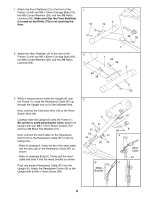
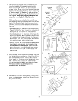
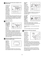
1. Attach the Front Stabilizer (2) to the front of the Frame (1) with two M8 x 70mm Carriage Bolts (72), two M8 Curved Washers (28), and two M8 Nylon Locknuts (56). Make sure that the Front Stabilizer is turned so the Roller (75) is not touching the floor. 1 72 2 75 28 56 2. Attach the Rear Stabilizer (3) to the rear of the Frame (1) with two M8 x 80mm Carriage Bolts (63), two M8 Curved Washers (28), and two M8 Nylon Locknuts (56). 1 2 1 56 28 3 56 28 3. While a second person holds the Upright (6) near the Frame (1), route the Resistance Cable (67) up through the Upright and out of the indicated hole. Next, connect the Extension Wire (18) to the Reed Switch Wire (44). Carefully slide the Upright (6) onto the Frame (1). Be careful to avoid pinching the wires. Attach the Upright with four M8 x 15mm Button Screws (74) and four M8 Black Flat Washers (57). Next, connect the short cable on the Resistance Control (8) to the Resistance Cable (67) in the following way: ¥ Refer to drawing A. Insert the tip of the short cable into the wire clip on the Resistance Cable (67) as shown. ¥ Refer to drawings B and C. Firmly pull the short cable and slide it into the metal bracket as shown. Push any excess Resistance Cable (67) into the Upright (6). Attach the Resistance Control (8) to the Upright with an M5 x 15mm Screw (69). 63 3 6 67 74 57 57 18 44 69 57 A 57 74 1 8 Short Cable B Metal Bracket 67 C 6
-
 1
1 -
 2
2 -
 3
3 -
 4
4 -
 5
5 -
 6
6 -
 7
7 -
 8
8 -
 9
9 -
 10
10 -
 11
11 -
 12
12 -
13
-
14
-
15
-
16
 |
 |
