HP 2000fc HP StorageWorks 2000 Family Modular Smart Array chassis and midplane - Page 1
HP 2000fc Manual
 |
View all HP 2000fc manuals
Add to My Manuals
Save this manual to your list of manuals |
Page 1 highlights
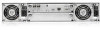
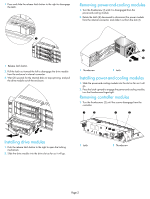
HP StorageWorks 2000 Family Modular Smart Array chassis and midplane replacement instructions Printed on at least 50% total recycled fiber with at least 10% post-consumer paper © Copyright 2008 Hewlett-Packard Development Company, L.P. First edition: March 2008 Product names mentioned herein may be trademarks of their respective companies as reflected by an associated footnote. The information in this document is subject to change without notice. Printed in the US. www.hp.com About this document The chassis field replacement unit (FRU) replaces a chassis that has been damaged or whose midplane has been damaged. To make a fully functional chassis, you must install the following components from the replaced chassis: • Drive modules and air management modules • Two power-and-cooling modules • One or two controller modules (for a controller enclosure) • One or two I/O modules (for a drive enclosure) This document details procedures for removing drive modules/air management modules, power-and cooling-modules, controller modules, and I/O modules from the failed chassis and installing them into the replacement chassis of an HP StorageWorks 2000 Family Modular Smart Array. NOTE: Make sure you obtain the latest version of these instructions from http://www.hp.com/go/msa. Select MSA SAN Arrays, select your product, and go to Support. Before you begin • Turn the power-and-cooling supply modules off and disconnect the power cables. • Disconnect and label all cables. CAUTION: Parts can be damaged by electrostatic discharge. Use proper anti-static protection: • Keep the replacement component in the ESD bag until needed. • Wear an ESD wrist strap grounded to an unpainted surface of the chassis. • If an ESD wrist strap is unavailable, touch an unpainted surface of the chassis before handling the component. • Never touch connector pins. Removing drive modules NOTE: Air management modules are removed and installed using the same procedure as removing and installing drive modules. 481596-001 Page 1
-
 1
1 -
 2
2 -
 3
3 -
 4
4
 |
 |