HP 273914-B21 Smart Array 6400 Series Controllers for Integrity Servers User G - Page 30
Diagnosing array problems, Controller board runtime LEDs
 |
UPC - 613326361313
View all HP 273914-B21 manuals
Add to My Manuals
Save this manual to your list of manuals |
Page 30 highlights
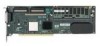
Diagnosing array problems In this section Controller board runtime LEDs...30 Cache module LEDs...31 Diagnostic tools ...32 Controller board runtime LEDs NOTE: During server power-up, each runtime LED illuminates randomly until POST has finished. LED ID 0 1 2 3 4 5 6 7 Color Amber Amber Blue Green Green Blue Green Green LED name and interpretation CR100: Diagnostics Error LED. CR101: Drive Failure LED. A physical drive connected to the controller has failed. CR102: SCSI Bus Active LED. At least one of the SCSI buses on the controller is active. CR103: XOR Active LED. The controller is calculating parity data. CR104: Command Outstanding LED. The controller is working on a command. CR105: Heartbeat LED. This LED flashes every 2 seconds, unless the controller is malfunctioning. CR106: Gas Pedal LED. This LED, together with item 7, indicates the amount of controller CPU activity. For details, refer to the following table. CR107: Idle Task LED. This LED, together with item 6, indicates the amount of controller CPU activity. For details, refer to the following table. Diagnosing array problems 30
-
 1
1 -
2
-
3
-
4
-
5
-
6
-
7
-
8
-
9
-
10
-
11
-
12
-
13
-
14
-
15
-
16
-
17
-
18
-
19
-
20
-
21
-
22
-
23
-
24
-
 25
25 -
 26
26 -
 27
27 -
 28
28 -
 29
29 -
 30
30 -
 31
31 -
 32
32 -
 33
33 -
 34
34 -
 35
35 -
36
-
37
-
38
-
39
-
40
-
41
-
42
 |
 |
