HP 3PAR StoreServ 7400 2-node HP 3PAR StoreServ 7000/7450 Storage Cabling Conf
HP 3PAR StoreServ 7400 2-node Manual
 |
View all HP 3PAR StoreServ 7400 2-node manuals
Add to My Manuals
Save this manual to your list of manuals |
HP 3PAR StoreServ 7400 2-node manual content summary:
- HP 3PAR StoreServ 7400 2-node | HP 3PAR StoreServ 7000/7450 Storage Cabling Conf - Page 1
HP 3PAR StoreServ 7000/7450 Storage Cabling Configuration Guide F: 4 Node Systems with Mixed-Size Drive Enclosures Abstract This guide provides cabling information for authorized technicians performing installation and maintenance services on the HP 3PAR StoreServ 7000/7450 Storage systems. HP Part - HP 3PAR StoreServ 7400 2-node | HP 3PAR StoreServ 7000/7450 Storage Cabling Conf - Page 2
to change without notice. The only warranties for HP products and services are set forth in the express warranty statements accompanying such products and services. Nothing herein should be construed as constituting an additional warranty. HP shall not be liable for technical or editorial errors - HP 3PAR StoreServ 7400 2-node | HP 3PAR StoreServ 7000/7450 Storage Cabling Conf - Page 3
Contents 1 Cabling Preparation for HP 3PAR StoreServ 7000/7450 8 Following Precautions...8 Identifying and Labeling the Components 8 2 Cabling HP 3PAR StoreServ 7000/7450 11 4 Node 4 Drive Enclosures (2S+2L 11 Attach DP-1 Chains to Enclosures 12 Attach DP-2 Chains to Enclosures 13 Review - HP 3PAR StoreServ 7400 2-node | HP 3PAR StoreServ 7000/7450 Storage Cabling Conf - Page 4
Enclosures (6S+6L 63 Attach DP-1 Chains to Enclosures 116 Attach DP-2 Chains to Enclosures 117 Review Completed Cabling 118 4 Node Interconnect Cabling 119 4 Node 12 Drive Enclosures (8S+4L 68 Attach DP-1 Chains to Enclosures 116 Attach DP-2 Chains to Enclosures 117 Review Completed Cabling - HP 3PAR StoreServ 7400 2-node | HP 3PAR StoreServ 7000/7450 Storage Cabling Conf - Page 5
Enclosures (12S+2L 115 Attach DP-1 Chains to Enclosures 116 Attach DP-2 Chains to Enclosures 117 Review Completed Cabling 118 4 Node Interconnect Cabling 119 4 Node 16 Drive Enclosures (2S+14L 120 Attach DP-1 Chains to Enclosures 230 Attach DP-1 Chains to Enclosures Between Racks 231 Attach - HP 3PAR StoreServ 7400 2-node | HP 3PAR StoreServ 7000/7450 Storage Cabling Conf - Page 6
Enclosures (14S+2L 168 Attach DP-1 Chains to Enclosures 169 Attach DP-2 Chains to Enclosures 170 Review Completed Cabling 171 4 Node Interconnect Cabling 236 4 Node 18 Drive Enclosures (2S+16L 173 Attach DP-1 Chains to Enclosures 230 Attach DP-1 Chains to Enclosures Between Racks 231 Attach - HP 3PAR StoreServ 7400 2-node | HP 3PAR StoreServ 7000/7450 Storage Cabling Conf - Page 7
-2 Chains to Enclosures 232 Attach DP-2 Chains to Enclosures Between Rack 233 Review Completed Cabling 234 Review Completed Cabling Between Racks 235 4 Node Interconnect Cabling 236 3 Additional Resources and Related Documentation 237 Contacting HP...237 HP 3PAR Documentation...237 Contents 7 - HP 3PAR StoreServ 7400 2-node | HP 3PAR StoreServ 7000/7450 Storage Cabling Conf - Page 8
while servicing the HP 3PAR StoreServ Storage system: • guide. The guide provides instructional guidance for cabling the HP 3PAR StoreServ 7000/7450 according to a specific configuration. All HP 3PAR StoreServ Storage systems contain either the HP 3PAR 7200 (2 nodes) or 7400/7450 (with 2 or 4 nodes - HP 3PAR StoreServ 7400 2-node | HP 3PAR StoreServ 7000/7450 Storage Cabling Conf - Page 9
Types of Components Use the red and green color coding to assist with the cabling. Only connect to components sharing the same color. Figure 1 Identifying Components and SAS Ports Identifying and Labeling the Components 9 - HP 3PAR StoreServ 7400 2-node | HP 3PAR StoreServ 7000/7450 Storage Cabling Conf - Page 10
depiction may not reflect the configuration setup of your system but the labeling pattern is similar. Figure 2 Labeling the Enclosures For more information relating to cabling hosts, refer to HP 3PAR StoreServ 7000/7450 Installation Guide. 10 Cabling Preparation for HP 3PAR StoreServ 7000/7450 - HP 3PAR StoreServ 7400 2-node | HP 3PAR StoreServ 7000/7450 Storage Cabling Conf - Page 11
2 Cabling HP 3PAR StoreServ 7000/7450 The following illustrative sections provide a rear view of the rack with recommended racking configuration of the system. 4 Node 4 Drive Enclosures (2S+2L) Before you begin cabling the storage system, carefully read or print the following section, including - HP 3PAR StoreServ 7400 2-node | HP 3PAR StoreServ 7000/7450 Storage Cabling Conf - Page 12
the controller. 3. Connect Node 3 (DP-1) to I/O 1 (DP-1) on the C drive enclosure farthest from the controller. 4. Connect all C drive enclosures from (DP-2) to (DP-1) working toward the controller. NOTE: The two adjacent enclosures are not directly connected. 12 Cabling HP 3PAR StoreServ 7000/7450 - HP 3PAR StoreServ 7400 2-node | HP 3PAR StoreServ 7000/7450 Storage Cabling Conf - Page 13
the B drive enclosure closest to the controller. 2. Connect all B drive enclosures from (DP-2) to (DP-1) working away from the controller. 3. Connect Node 2 (DP-2) to the I/O 0 (DP-1) on the D drive enclosure closest to the controller. 4. Connect all D drive enclosures from (DP-2) to (DP-1) working - HP 3PAR StoreServ 7400 2-node | HP 3PAR StoreServ 7000/7450 Storage Cabling Conf - Page 14
Review Completed Cabling 14 Cabling HP 3PAR StoreServ 7000/7450 - HP 3PAR StoreServ 7400 2-node | HP 3PAR StoreServ 7000/7450 Storage Cabling Conf - Page 15
4 Node 6 Drive Enclosures (2S+4L) Before you begin cabling the storage system, carefully read or print the following section, including figures 1 and 2, "Identifying and Labeling the Components" (page 8). 4 Node 6 Drive Enclosures (2S+4L) 15 - HP 3PAR StoreServ 7400 2-node | HP 3PAR StoreServ 7000/7450 Storage Cabling Conf - Page 16
the controller. 3. Connect Node 3 (DP-1) to I/O 1 (DP-1) on the C drive enclosure farthest from the controller. 4. Connect all C drive enclosures from (DP-2) to (DP-1) working toward the controller. NOTE: The two adjacent enclosures are not directly connected. 16 Cabling HP 3PAR StoreServ 7000/7450 - HP 3PAR StoreServ 7400 2-node | HP 3PAR StoreServ 7000/7450 Storage Cabling Conf - Page 17
the B drive enclosure closest to the controller. 2. Connect all B drive enclosures from (DP-2) to (DP-1) working away from the controller. 3. Connect Node 2 (DP-2) to the I/O 0 (DP-1) on the D drive enclosure closest to the controller. 4. Connect all D drive enclosures from (DP-2) to (DP-1) working - HP 3PAR StoreServ 7400 2-node | HP 3PAR StoreServ 7000/7450 Storage Cabling Conf - Page 18
Review Completed Cabling 18 Cabling HP 3PAR StoreServ 7000/7450 - HP 3PAR StoreServ 7400 2-node | HP 3PAR StoreServ 7000/7450 Storage Cabling Conf - Page 19
4 Node 6 Drive Enclosures (4S+2L) Before you begin cabling the storage system, carefully read or print the following section, including figures 1 and 2, "Identifying and Labeling the Components" (page 8). 4 Node 6 Drive Enclosures (4S+2L) 19 - HP 3PAR StoreServ 7400 2-node | HP 3PAR StoreServ 7000/7450 Storage Cabling Conf - Page 20
the controller. 3. Connect Node 3 (DP-1) to I/O 1 (DP-1) on the C drive enclosure farthest from the controller. 4. Connect all C drive enclosures from (DP-2) to (DP-1) working toward the controller. NOTE: The two adjacent enclosures are not directly connected. 20 Cabling HP 3PAR StoreServ 7000/7450 - HP 3PAR StoreServ 7400 2-node | HP 3PAR StoreServ 7000/7450 Storage Cabling Conf - Page 21
the B drive enclosure closest to the controller. 2. Connect all B drive enclosures from (DP-2) to (DP-1) working away from the controller. 3. Connect Node 2 (DP-2) to the I/O 0 (DP-1) on the D drive enclosure closest to the controller. 4. Connect all D drive enclosures from (DP-2) to (DP-1) working - HP 3PAR StoreServ 7400 2-node | HP 3PAR StoreServ 7000/7450 Storage Cabling Conf - Page 22
Review Completed Cabling 22 Cabling HP 3PAR StoreServ 7000/7450 - HP 3PAR StoreServ 7400 2-node | HP 3PAR StoreServ 7000/7450 Storage Cabling Conf - Page 23
Intr 0 to Controller C, Node 3, Intr 1 4. Controller A, Node 1, Intr 1 to Controller C, Node 2, Intr 0 The completed cabling is shown below. After confirming all cabling is correct (SAS and interconnection), the system may be powered on by using procedures from the installation guide. CAUTION: The - HP 3PAR StoreServ 7400 2-node | HP 3PAR StoreServ 7000/7450 Storage Cabling Conf - Page 24
4 Node 8 Drive Enclosures (2S+6L) Before you begin cabling the storage system, carefully read or print the following section, including figures 1 and 2, "Identifying and Labeling the Components" (page 8). 24 Cabling HP 3PAR StoreServ 7000/7450 - HP 3PAR StoreServ 7400 2-node | HP 3PAR StoreServ 7000/7450 Storage Cabling Conf - Page 25
the A drive enclosure closest to the controller. 2. Connect all A drive enclosures from (DP-2) to (DP-1) working away from the controller. 3. Connect Node 2 (DP-1) to the I/O 0 (DP-1) on the C drive enclosure closest to the controller. 4. Connect all C drive enclosures from (DP-2) to (DP-1) working - HP 3PAR StoreServ 7400 2-node | HP 3PAR StoreServ 7000/7450 Storage Cabling Conf - Page 26
the controller. 3. Connect Node 3 (DP-2) to I/O 1 (DP-1) on the D drive enclosure farthest from the controller. 4. Connect all D drive enclosures from (DP-2) to (DP-1) working toward the controller. NOTE: The two adjacent enclosures are not directly connected. 26 Cabling HP 3PAR StoreServ 7000/7450 - HP 3PAR StoreServ 7400 2-node | HP 3PAR StoreServ 7000/7450 Storage Cabling Conf - Page 27
Review Completed Cabling 4 Node 8 Drive Enclosures (2S+6L) 27 - HP 3PAR StoreServ 7400 2-node | HP 3PAR StoreServ 7000/7450 Storage Cabling Conf - Page 28
0 The completed cabling is shown below. After confirming all cabling is correct (SAS and interconnection), the system may be powered on by using procedures from the installation guide. CAUTION: The Interconnect Link Cables are directional and labeled A and C. 28 Cabling HP 3PAR StoreServ 7000/7450 - HP 3PAR StoreServ 7400 2-node | HP 3PAR StoreServ 7000/7450 Storage Cabling Conf - Page 29
4 Node 8 Drive Enclosures (4S+4L) Before you begin cabling the storage system, carefully read or print the following section, including figures 1 and 2, "Identifying and Labeling the Components" (page 8). 4 Node 8 Drive Enclosures (4S+4L) 29 - HP 3PAR StoreServ 7400 2-node | HP 3PAR StoreServ 7000/7450 Storage Cabling Conf - Page 30
the controller. 3. Connect Node 3 (DP-1) to I/O 1 (DP-1) on the C drive enclosure farthest from the controller. 4. Connect all C drive enclosures from (DP-2) to (DP-1) working toward the controller. NOTE: The two adjacent enclosures are not directly connected. 30 Cabling HP 3PAR StoreServ 7000/7450 - HP 3PAR StoreServ 7400 2-node | HP 3PAR StoreServ 7000/7450 Storage Cabling Conf - Page 31
the B drive enclosure closest to the controller. 2. Connect all B drive enclosures from (DP-2) to (DP-1) working away from the controller. 3. Connect Node 2 (DP-2) to the I/O 0 (DP-1) on the D drive enclosure closest to the controller. 4. Connect all D drive enclosures from (DP-2) to (DP-1) working - HP 3PAR StoreServ 7400 2-node | HP 3PAR StoreServ 7000/7450 Storage Cabling Conf - Page 32
Review Completed Cabling 32 Cabling HP 3PAR StoreServ 7000/7450 - HP 3PAR StoreServ 7400 2-node | HP 3PAR StoreServ 7000/7450 Storage Cabling Conf - Page 33
Intr 0 to Controller C, Node 3, Intr 1 4. Controller A, Node 1, Intr 1 to Controller C, Node 2, Intr 0 The completed cabling is shown below. After confirming all cabling is correct (SAS and interconnection), the system may be powered on by using procedures from the installation guide. CAUTION: The - HP 3PAR StoreServ 7400 2-node | HP 3PAR StoreServ 7000/7450 Storage Cabling Conf - Page 34
4 Node 10 Drive Enclosures (2S+8L) Before you begin cabling the storage system, carefully read or print the following section, including figures 1 and 2, "Identifying and Labeling the Components" (page 8). 34 Cabling HP 3PAR StoreServ 7000/7450 - HP 3PAR StoreServ 7400 2-node | HP 3PAR StoreServ 7000/7450 Storage Cabling Conf - Page 35
the A drive enclosure closest to the controller. 2. Connect all A drive enclosures from (DP-2) to (DP-1) working away from the controller. 3. Connect Node 2 (DP-1) to the I/O 0 (DP-1) on the C drive enclosure closest to the controller. 4. Connect all C drive enclosures from (DP-2) to (DP-1) working - HP 3PAR StoreServ 7400 2-node | HP 3PAR StoreServ 7000/7450 Storage Cabling Conf - Page 36
the controller. 3. Connect Node 3 (DP-2) to I/O 1 (DP-1) on the D drive enclosure farthest from the controller. 4. Connect all D drive enclosures from (DP-2) to (DP-1) working toward the controller. NOTE: The two adjacent enclosures are not directly connected. 36 Cabling HP 3PAR StoreServ 7000/7450 - HP 3PAR StoreServ 7400 2-node | HP 3PAR StoreServ 7000/7450 Storage Cabling Conf - Page 37
Review Completed Cabling 4 Node 10 Drive Enclosures (2S+8L) 37 - HP 3PAR StoreServ 7400 2-node | HP 3PAR StoreServ 7000/7450 Storage Cabling Conf - Page 38
4 Node 10 Drive Enclosures (6S+4L) Before you begin cabling the storage system, carefully read or print the following section, including figures 1 and 2, "Identifying and Labeling the Components" (page 8). 38 Cabling HP 3PAR StoreServ 7000/7450 - HP 3PAR StoreServ 7400 2-node | HP 3PAR StoreServ 7000/7450 Storage Cabling Conf - Page 39
the A drive enclosure closest to the controller. 2. Connect all A drive enclosures from (DP-2) to (DP-1) working away from the controller. 3. Connect Node 2 (DP-1) to the I/O 0 (DP-1) on the C drive enclosure closest to the controller. 4. Connect all C drive enclosures from (DP-2) to (DP-1) working - HP 3PAR StoreServ 7400 2-node | HP 3PAR StoreServ 7000/7450 Storage Cabling Conf - Page 40
the controller. 3. Connect Node 3 (DP-2) to I/O 1 (DP-1) on the D drive enclosure farthest from the controller. 4. Connect all D drive enclosures from (DP-2) to (DP-1) working toward the controller. NOTE: The two adjacent enclosures are not directly connected. 40 Cabling HP 3PAR StoreServ 7000/7450 - HP 3PAR StoreServ 7400 2-node | HP 3PAR StoreServ 7000/7450 Storage Cabling Conf - Page 41
Review Completed Cabling 4 Node 10 Drive Enclosures (6S+4L) 41 - HP 3PAR StoreServ 7400 2-node | HP 3PAR StoreServ 7000/7450 Storage Cabling Conf - Page 42
4 Node 10 Drive Enclosures (8S+2L) Before you begin cabling the storage system, carefully read or print the following section, including figures 1 and 2, "Identifying and Labeling the Components" (page 8). 42 Cabling HP 3PAR StoreServ 7000/7450 - HP 3PAR StoreServ 7400 2-node | HP 3PAR StoreServ 7000/7450 Storage Cabling Conf - Page 43
the A drive enclosure closest to the controller. 2. Connect all A drive enclosures from (DP-2) to (DP-1) working away from the controller. 3. Connect Node 2 (DP-1) to the I/O 0 (DP-1) on the C drive enclosure closest to the controller. 4. Connect all C drive enclosures from (DP-2) to (DP-1) working - HP 3PAR StoreServ 7400 2-node | HP 3PAR StoreServ 7000/7450 Storage Cabling Conf - Page 44
the controller. 3. Connect Node 3 (DP-2) to I/O 1 (DP-1) on the D drive enclosure farthest from the controller. 4. Connect all D drive enclosures from (DP-2) to (DP-1) working toward the controller. NOTE: The two adjacent enclosures are not directly connected. 44 Cabling HP 3PAR StoreServ 7000/7450 - HP 3PAR StoreServ 7400 2-node | HP 3PAR StoreServ 7000/7450 Storage Cabling Conf - Page 45
Review Completed Cabling 4 Node 10 Drive Enclosures (8S+2L) 45 - HP 3PAR StoreServ 7400 2-node | HP 3PAR StoreServ 7000/7450 Storage Cabling Conf - Page 46
0 The completed cabling is shown below. After confirming all cabling is correct (SAS and interconnection), the system may be powered on by using procedures from the installation guide. CAUTION: The Interconnect Link Cables are directional and labeled A and C. 46 Cabling HP 3PAR StoreServ 7000/7450 - HP 3PAR StoreServ 7400 2-node | HP 3PAR StoreServ 7000/7450 Storage Cabling Conf - Page 47
4 Node 12 Drive Enclosures (2S+10L) Before you begin cabling the storage system, carefully read or print the following section, including figures 1 and 2, "Identifying and Labeling the Components" (page 8). 4 Node 12 Drive Enclosures (2S+10L) 47 - HP 3PAR StoreServ 7400 2-node | HP 3PAR StoreServ 7000/7450 Storage Cabling Conf - Page 48
. Green routing 1. Connect Node 3 (DP-1) to I/O 1 (DP-1) on the C drive enclosure farthest from the controller. 2. Connect all C drive enclosures from (DP-2) to (DP-1) working toward the controller. NOTE: The two adjacent enclosures are not directly connected. 48 Cabling HP 3PAR StoreServ 7000/7450 - HP 3PAR StoreServ 7400 2-node | HP 3PAR StoreServ 7000/7450 Storage Cabling Conf - Page 49
Attach DP-1 Chains to Enclosures Between Racks Six meter (6m) cables must be used for connections between racks. Red routing 1. Connect Node 0 (DP-1) to the I/O 0 (DP-1) on the A drive enclosure closest to the controller. 2. Connect all A drive enclosures from (DP-2) to (DP-1) working away from the - HP 3PAR StoreServ 7400 2-node | HP 3PAR StoreServ 7000/7450 Storage Cabling Conf - Page 50
. Green routing 1. Connect Node 3 (DP-2) to I/O 1 (DP-1) on the D drive enclosure farthest from the controller. 2. Connect all D drive enclosures from (DP-2) to (DP-1) working toward the controller. NOTE: The two adjacent enclosures are not directly connected. 50 Cabling HP 3PAR StoreServ 7000/7450 - HP 3PAR StoreServ 7400 2-node | HP 3PAR StoreServ 7000/7450 Storage Cabling Conf - Page 51
Attach DP-2 Chains to Enclosures Between Racks Six meter (6m) cables must be used for connections between racks. Red routing 1. Connect Node 0 (DP-2) to the I/O 0 (DP-1) on the B drive enclosure closest to the controller. 2. Connect all B drive enclosures from (DP-2) to (DP-1) working away from the - HP 3PAR StoreServ 7400 2-node | HP 3PAR StoreServ 7000/7450 Storage Cabling Conf - Page 52
Review Completed Cabling 52 Cabling HP 3PAR StoreServ 7000/7450 - HP 3PAR StoreServ 7400 2-node | HP 3PAR StoreServ 7000/7450 Storage Cabling Conf - Page 53
Review Completed Cabling Between Racks 4 Node 12 Drive Enclosures (2S+10L) 53 - HP 3PAR StoreServ 7400 2-node | HP 3PAR StoreServ 7000/7450 Storage Cabling Conf - Page 54
0 The completed cabling is shown below. After confirming all cabling is correct (SAS and interconnection), the system may be powered on by using procedures from the installation guide. CAUTION: The Interconnect Link Cables are directional and labeled A and C. 54 Cabling HP 3PAR StoreServ 7000/7450 - HP 3PAR StoreServ 7400 2-node | HP 3PAR StoreServ 7000/7450 Storage Cabling Conf - Page 55
4 Node 12 Drive Enclosures (4S+8L) Before you begin cabling the storage system, carefully read or print the following section, including figures 1 and 2, "Identifying and Labeling the Components" (page 8). 4 Node 12 Drive Enclosures (4S+8L) 55 - HP 3PAR StoreServ 7400 2-node | HP 3PAR StoreServ 7000/7450 Storage Cabling Conf - Page 56
. Green routing 1. Connect Node 3 (DP-1) to I/O 1 (DP-1) on the C drive enclosure farthest from the controller. 2. Connect all C drive enclosures from (DP-2) to (DP-1) working toward the controller. NOTE: The two adjacent enclosures are not directly connected. 56 Cabling HP 3PAR StoreServ 7000/7450 - HP 3PAR StoreServ 7400 2-node | HP 3PAR StoreServ 7000/7450 Storage Cabling Conf - Page 57
Attach DP-1 Chains to Enclosures Between Racks Six meter (6m) cables must be used for connections between racks. Red routing 1. Connect Node 0 (DP-1) to the I/O 0 (DP-1) on the A drive enclosure closest to the controller. 2. Connect all A drive enclosures from (DP-2) to (DP-1) working away from the - HP 3PAR StoreServ 7400 2-node | HP 3PAR StoreServ 7000/7450 Storage Cabling Conf - Page 58
. Green routing 1. Connect Node 3 (DP-2) to I/O 1 (DP-1) on the D drive enclosure farthest from the controller. 2. Connect all D drive enclosures from (DP-2) to (DP-1) working toward the controller. NOTE: The two adjacent enclosures are not directly connected. 58 Cabling HP 3PAR StoreServ 7000/7450 - HP 3PAR StoreServ 7400 2-node | HP 3PAR StoreServ 7000/7450 Storage Cabling Conf - Page 59
Attach DP-2 Chains to Enclosures Between Racks Six meter (6m) cables must be used for connections between racks. Red routing 1. Connect Node 0 (DP-2) to the I/O 0 (DP-1) on the B drive enclosure closest to the controller. 2. Connect all B drive enclosures from (DP-2) to (DP-1) working away from the - HP 3PAR StoreServ 7400 2-node | HP 3PAR StoreServ 7000/7450 Storage Cabling Conf - Page 60
Review Completed Cabling 60 Cabling HP 3PAR StoreServ 7000/7450 - HP 3PAR StoreServ 7400 2-node | HP 3PAR StoreServ 7000/7450 Storage Cabling Conf - Page 61
Review Completed Cabling Between Racks 4 Node 12 Drive Enclosures (4S+8L) 61 - HP 3PAR StoreServ 7400 2-node | HP 3PAR StoreServ 7000/7450 Storage Cabling Conf - Page 62
0 The completed cabling is shown below. After confirming all cabling is correct (SAS and interconnection), the system may be powered on by using procedures from the installation guide. CAUTION: The Interconnect Link Cables are directional and labeled A and C. 62 Cabling HP 3PAR StoreServ 7000/7450 - HP 3PAR StoreServ 7400 2-node | HP 3PAR StoreServ 7000/7450 Storage Cabling Conf - Page 63
4 Node 12 Drive Enclosures (6S+6L) Before you begin cabling the storage system, carefully read or print the following section, including figures 1 and 2, "Identifying and Labeling the Components" (page 8). 4 Node 12 Drive Enclosures (6S+6L) 63 - HP 3PAR StoreServ 7400 2-node | HP 3PAR StoreServ 7000/7450 Storage Cabling Conf - Page 64
the controller. 3. Connect Node 3 (DP-1) to I/O 1 (DP-1) on the C drive enclosure farthest from the controller. 4. Connect all C drive enclosures from (DP-2) to (DP-1) working toward the controller. NOTE: The two adjacent enclosures are not directly connected. 64 Cabling HP 3PAR StoreServ 7000/7450 - HP 3PAR StoreServ 7400 2-node | HP 3PAR StoreServ 7000/7450 Storage Cabling Conf - Page 65
the B drive enclosure closest to the controller. 2. Connect all B drive enclosures from (DP-2) to (DP-1) working away from the controller. 3. Connect Node 2 (DP-2) to the I/O 0 (DP-1) on the D drive enclosure closest to the controller. 4. Connect all D drive enclosures from (DP-2) to (DP-1) working - HP 3PAR StoreServ 7400 2-node | HP 3PAR StoreServ 7000/7450 Storage Cabling Conf - Page 66
Review Completed Cabling 66 Cabling HP 3PAR StoreServ 7000/7450 - HP 3PAR StoreServ 7400 2-node | HP 3PAR StoreServ 7000/7450 Storage Cabling Conf - Page 67
Intr 0 to Controller C, Node 3, Intr 1 4. Controller A, Node 1, Intr 1 to Controller C, Node 2, Intr 0 The completed cabling is shown below. After confirming all cabling is correct (SAS and interconnection), the system may be powered on by using procedures from the installation guide. CAUTION: The - HP 3PAR StoreServ 7400 2-node | HP 3PAR StoreServ 7000/7450 Storage Cabling Conf - Page 68
4 Node 12 Drive Enclosures (8S+4L) Before you begin cabling the storage system, carefully read or print the following section, including figures 1 and 2, "Identifying and Labeling the Components" (page 8). 68 Cabling HP 3PAR StoreServ 7000/7450 - HP 3PAR StoreServ 7400 2-node | HP 3PAR StoreServ 7000/7450 Storage Cabling Conf - Page 69
the A drive enclosure closest to the controller. 2. Connect all A drive enclosures from (DP-2) to (DP-1) working away from the controller. 3. Connect Node 2 (DP-1) to the I/O 0 (DP-1) on the C drive enclosure closest to the controller. 4. Connect all C drive enclosures from (DP-2) to (DP-1) working - HP 3PAR StoreServ 7400 2-node | HP 3PAR StoreServ 7000/7450 Storage Cabling Conf - Page 70
the controller. 3. Connect Node 3 (DP-2) to I/O 1 (DP-1) on the D drive enclosure farthest from the controller. 4. Connect all D drive enclosures from (DP-2) to (DP-1) working toward the controller. NOTE: The two adjacent enclosures are not directly connected. 70 Cabling HP 3PAR StoreServ 7000/7450 - HP 3PAR StoreServ 7400 2-node | HP 3PAR StoreServ 7000/7450 Storage Cabling Conf - Page 71
Review Completed Cabling 4 Node 12 Drive Enclosures (8S+4L) 71 - HP 3PAR StoreServ 7400 2-node | HP 3PAR StoreServ 7000/7450 Storage Cabling Conf - Page 72
0 The completed cabling is shown below. After confirming all cabling is correct (SAS and interconnection), the system may be powered on by using procedures from the installation guide. CAUTION: The Interconnect Link Cables are directional and labeled A and C. 72 Cabling HP 3PAR StoreServ 7000/7450 - HP 3PAR StoreServ 7400 2-node | HP 3PAR StoreServ 7000/7450 Storage Cabling Conf - Page 73
4 Node 12 Drive Enclosures (10S+2L) Before you begin cabling the storage system, carefully read or print the following section, including figures 1 and 2, "Identifying and Labeling the Components" (page 8). 4 Node 12 Drive Enclosures (10S+2L) 73 - HP 3PAR StoreServ 7400 2-node | HP 3PAR StoreServ 7000/7450 Storage Cabling Conf - Page 74
the controller. 3. Connect Node 3 (DP-1) to I/O 1 (DP-1) on the C drive enclosure farthest from the controller. 4. Connect all C drive enclosures from (DP-2) to (DP-1) working toward the controller. NOTE: The two adjacent enclosures are not directly connected. 74 Cabling HP 3PAR StoreServ 7000/7450 - HP 3PAR StoreServ 7400 2-node | HP 3PAR StoreServ 7000/7450 Storage Cabling Conf - Page 75
the B drive enclosure closest to the controller. 2. Connect all B drive enclosures from (DP-2) to (DP-1) working away from the controller. 3. Connect Node 2 (DP-2) to the I/O 0 (DP-1) on the D drive enclosure closest to the controller. 4. Connect all D drive enclosures from (DP-2) to (DP-1) working - HP 3PAR StoreServ 7400 2-node | HP 3PAR StoreServ 7000/7450 Storage Cabling Conf - Page 76
Review Completed Cabling 76 Cabling HP 3PAR StoreServ 7000/7450 - HP 3PAR StoreServ 7400 2-node | HP 3PAR StoreServ 7000/7450 Storage Cabling Conf - Page 77
Intr 0 to Controller C, Node 3, Intr 1 4. Controller A, Node 1, Intr 1 to Controller C, Node 2, Intr 0 The completed cabling is shown below. After confirming all cabling is correct (SAS and interconnection), the system may be powered on by using procedures from the installation guide. CAUTION: The - HP 3PAR StoreServ 7400 2-node | HP 3PAR StoreServ 7000/7450 Storage Cabling Conf - Page 78
4 Node 14 Drive Enclosures (2S+12L) Before you begin cabling the storage system, carefully read or print the following section, including figures 1 and 2, "Identifying and Labeling the Components" (page 8). 78 Cabling HP 3PAR StoreServ 7000/7450 - HP 3PAR StoreServ 7400 2-node | HP 3PAR StoreServ 7000/7450 Storage Cabling Conf - Page 79
enclosure closest to the controller. 2. Connect all C drive enclosures from (DP-2) to (DP-1) working away from the controller. Green routing 1. Connect Node 3 (DP-1) to I/O 1 (DP-1) on the C drive enclosure farthest from the controller. 2. Connect all C drive enclosures from (DP-2) to (DP-1) working - HP 3PAR StoreServ 7400 2-node | HP 3PAR StoreServ 7000/7450 Storage Cabling Conf - Page 80
. Green routing 1. Connect Node 1 (DP-1) to I/O 1 (DP-1) on the A drive enclosure farthest from the controller. 2. Connect all A drive enclosures from (DP-2) to (DP-1) working toward the controller. NOTE: The two adjacent enclosures are not directly connected. 80 Cabling HP 3PAR StoreServ 7000/7450 - HP 3PAR StoreServ 7400 2-node | HP 3PAR StoreServ 7000/7450 Storage Cabling Conf - Page 81
enclosure closest to the controller. 2. Connect all D drive enclosures from (DP-2) to (DP-1) working away from the controller. Green routing 1. Connect Node 3 (DP-2) to I/O 1 (DP-1) on the D drive enclosure farthest from the controller. 2. Connect all D drive enclosures from (DP-2) to (DP-1) working - HP 3PAR StoreServ 7400 2-node | HP 3PAR StoreServ 7000/7450 Storage Cabling Conf - Page 82
. Green routing 1. Connect Node 1 (DP-2) to I/O 1 (DP-1) on the B drive enclosure farthest from the controller. 2. Connect all B drive enclosures from (DP-2) to (DP-1) working toward the controller. NOTE: The two adjacent enclosures are not directly connected. 82 Cabling HP 3PAR StoreServ 7000/7450 - HP 3PAR StoreServ 7400 2-node | HP 3PAR StoreServ 7000/7450 Storage Cabling Conf - Page 83
Review Completed Cabling 4 Node 14 Drive Enclosures (2S+12L) 83 - HP 3PAR StoreServ 7400 2-node | HP 3PAR StoreServ 7000/7450 Storage Cabling Conf - Page 84
Review Completed Cabling Between Racks 84 Cabling HP 3PAR StoreServ 7000/7450 - HP 3PAR StoreServ 7400 2-node | HP 3PAR StoreServ 7000/7450 Storage Cabling Conf - Page 85
Intr 0 to Controller C, Node 3, Intr 1 4. Controller A, Node 1, Intr 1 to Controller C, Node 2, Intr 0 The completed cabling is shown below. After confirming all cabling is correct (SAS and interconnection), the system may be powered on by using procedures from the installation guide. CAUTION: The - HP 3PAR StoreServ 7400 2-node | HP 3PAR StoreServ 7000/7450 Storage Cabling Conf - Page 86
4 Node 14 Drive Enclosures (4S+10L) Before you begin cabling the storage system, carefully read or print the following section, including figures 1 and 2, "Identifying and Labeling the Components" (page 8). 86 Cabling HP 3PAR StoreServ 7000/7450 - HP 3PAR StoreServ 7400 2-node | HP 3PAR StoreServ 7000/7450 Storage Cabling Conf - Page 87
enclosure closest to the controller. 2. Connect all C drive enclosures from (DP-2) to (DP-1) working away from the controller. Green routing 1. Connect Node 3 (DP-1) to I/O 1 (DP-1) on the C drive enclosure farthest from the controller. 2. Connect all C drive enclosures from (DP-2) to (DP-1) working - HP 3PAR StoreServ 7400 2-node | HP 3PAR StoreServ 7000/7450 Storage Cabling Conf - Page 88
. Green routing 1. Connect Node 1 (DP-1) to I/O 1 (DP-1) on the A drive enclosure farthest from the controller. 2. Connect all A drive enclosures from (DP-2) to (DP-1) working toward the controller. NOTE: The two adjacent enclosures are not directly connected. 88 Cabling HP 3PAR StoreServ 7000/7450 - HP 3PAR StoreServ 7400 2-node | HP 3PAR StoreServ 7000/7450 Storage Cabling Conf - Page 89
enclosure closest to the controller. 2. Connect all D drive enclosures from (DP-2) to (DP-1) working away from the controller. Green routing 1. Connect Node 3 (DP-2) to I/O 1 (DP-1) on the D drive enclosure farthest from the controller. 2. Connect all D drive enclosures from (DP-2) to (DP-1) working - HP 3PAR StoreServ 7400 2-node | HP 3PAR StoreServ 7000/7450 Storage Cabling Conf - Page 90
. Green routing 1. Connect Node 1 (DP-2) to I/O 1 (DP-1) on the B drive enclosure farthest from the controller. 2. Connect all B drive enclosures from (DP-2) to (DP-1) working toward the controller. NOTE: The two adjacent enclosures are not directly connected. 90 Cabling HP 3PAR StoreServ 7000/7450 - HP 3PAR StoreServ 7400 2-node | HP 3PAR StoreServ 7000/7450 Storage Cabling Conf - Page 91
Review Completed Cabling 4 Node 14 Drive Enclosures (4S+10L) 91 - HP 3PAR StoreServ 7400 2-node | HP 3PAR StoreServ 7000/7450 Storage Cabling Conf - Page 92
Review Completed Cabling Between Racks 92 Cabling HP 3PAR StoreServ 7000/7450 - HP 3PAR StoreServ 7400 2-node | HP 3PAR StoreServ 7000/7450 Storage Cabling Conf - Page 93
Intr 0 to Controller C, Node 3, Intr 1 4. Controller A, Node 1, Intr 1 to Controller C, Node 2, Intr 0 The completed cabling is shown below. After confirming all cabling is correct (SAS and interconnection), the system may be powered on by using procedures from the installation guide. CAUTION: The - HP 3PAR StoreServ 7400 2-node | HP 3PAR StoreServ 7000/7450 Storage Cabling Conf - Page 94
4 Node 14 Drive Enclosures (6S+8L) Before you begin cabling the storage system, carefully read or print the following section, including figures 1 and 2, "Identifying and Labeling the Components" (page 8). 94 Cabling HP 3PAR StoreServ 7000/7450 - HP 3PAR StoreServ 7400 2-node | HP 3PAR StoreServ 7000/7450 Storage Cabling Conf - Page 95
enclosure closest to the controller. 2. Connect all C drive enclosures from (DP-2) to (DP-1) working away from the controller. Green routing 1. Connect Node 3 (DP-1) to I/O 1 (DP-1) on the C drive enclosure farthest from the controller. 2. Connect all C drive enclosures from (DP-2) to (DP-1) working - HP 3PAR StoreServ 7400 2-node | HP 3PAR StoreServ 7000/7450 Storage Cabling Conf - Page 96
. Green routing 1. Connect Node 1 (DP-1) to I/O 1 (DP-1) on the A drive enclosure farthest from the controller. 2. Connect all A drive enclosures from (DP-2) to (DP-1) working toward the controller. NOTE: The two adjacent enclosures are not directly connected. 96 Cabling HP 3PAR StoreServ 7000/7450 - HP 3PAR StoreServ 7400 2-node | HP 3PAR StoreServ 7000/7450 Storage Cabling Conf - Page 97
enclosure closest to the controller. 2. Connect all D drive enclosures from (DP-2) to (DP-1) working away from the controller. Green routing 1. Connect Node 3 (DP-2) to I/O 1 (DP-1) on the D drive enclosure farthest from the controller. 2. Connect all D drive enclosures from (DP-2) to (DP-1) working - HP 3PAR StoreServ 7400 2-node | HP 3PAR StoreServ 7000/7450 Storage Cabling Conf - Page 98
. Green routing 1. Connect Node 1 (DP-2) to I/O 1 (DP-1) on the B drive enclosure farthest from the controller. 2. Connect all B drive enclosures from (DP-2) to (DP-1) working toward the controller. NOTE: The two adjacent enclosures are not directly connected. 98 Cabling HP 3PAR StoreServ 7000/7450 - HP 3PAR StoreServ 7400 2-node | HP 3PAR StoreServ 7000/7450 Storage Cabling Conf - Page 99
Review Completed Cabling 4 Node 14 Drive Enclosures (6S+8L) 99 - HP 3PAR StoreServ 7400 2-node | HP 3PAR StoreServ 7000/7450 Storage Cabling Conf - Page 100
Review Completed Cabling Between Racks 100 Cabling HP 3PAR StoreServ 7000/7450 - HP 3PAR StoreServ 7400 2-node | HP 3PAR StoreServ 7000/7450 Storage Cabling Conf - Page 101
Intr 0 to Controller C, Node 3, Intr 1 4. Controller A, Node 1, Intr 1 to Controller C, Node 2, Intr 0 The completed cabling is shown below. After confirming all cabling is correct (SAS and interconnection), the system may be powered on by using procedures from the installation guide. CAUTION: The - HP 3PAR StoreServ 7400 2-node | HP 3PAR StoreServ 7000/7450 Storage Cabling Conf - Page 102
4 Node 14 Drive Enclosures (8S+6L) Before you begin cabling the storage system, carefully read or print the following section, including figures 1 and 2, "Identifying and Labeling the Components" (page 8). 102 Cabling HP 3PAR StoreServ 7000/7450 - HP 3PAR StoreServ 7400 2-node | HP 3PAR StoreServ 7000/7450 Storage Cabling Conf - Page 103
enclosure closest to the controller. 2. Connect all C drive enclosures from (DP-2) to (DP-1) working away from the controller. Green routing 1. Connect Node 3 (DP-1) to I/O 1 (DP-1) on the C drive enclosure farthest from the controller. 2. Connect all C drive enclosures from (DP-2) to (DP-1) working - HP 3PAR StoreServ 7400 2-node | HP 3PAR StoreServ 7000/7450 Storage Cabling Conf - Page 104
. Green routing 1. Connect Node 1 (DP-1) to I/O 1 (DP-1) on the A drive enclosure farthest from the controller. 2. Connect all A drive enclosures from (DP-2) to (DP-1) working toward the controller. NOTE: The two adjacent enclosures are not directly connected. 104 Cabling HP 3PAR StoreServ 7000/7450 - HP 3PAR StoreServ 7400 2-node | HP 3PAR StoreServ 7000/7450 Storage Cabling Conf - Page 105
enclosure closest to the controller. 2. Connect all D drive enclosures from (DP-2) to (DP-1) working away from the controller. Green routing 1. Connect Node 3 (DP-2) to I/O 1 (DP-1) on the D drive enclosure farthest from the controller. 2. Connect all D drive enclosures from (DP-2) to (DP-1) working - HP 3PAR StoreServ 7400 2-node | HP 3PAR StoreServ 7000/7450 Storage Cabling Conf - Page 106
. Green routing 1. Connect Node 1 (DP-2) to I/O 1 (DP-1) on the B drive enclosure farthest from the controller. 2. Connect all B drive enclosures from (DP-2) to (DP-1) working toward the controller. NOTE: The two adjacent enclosures are not directly connected. 106 Cabling HP 3PAR StoreServ 7000/7450 - HP 3PAR StoreServ 7400 2-node | HP 3PAR StoreServ 7000/7450 Storage Cabling Conf - Page 107
Review Completed Cabling 4 Node 14 Drive Enclosures (8S+6L) 107 - HP 3PAR StoreServ 7400 2-node | HP 3PAR StoreServ 7000/7450 Storage Cabling Conf - Page 108
Review Completed Cabling Between Racks 108 Cabling HP 3PAR StoreServ 7000/7450 - HP 3PAR StoreServ 7400 2-node | HP 3PAR StoreServ 7000/7450 Storage Cabling Conf - Page 109
Intr 0 to Controller C, Node 3, Intr 1 4. Controller A, Node 1, Intr 1 to Controller C, Node 2, Intr 0 The completed cabling is shown below. After confirming all cabling is correct (SAS and interconnection), the system may be powered on by using procedures from the installation guide. CAUTION: The - HP 3PAR StoreServ 7400 2-node | HP 3PAR StoreServ 7000/7450 Storage Cabling Conf - Page 110
4 Node 14 Drive Enclosures (10S+4L) Before you begin cabling the storage system, carefully read or print the following section, including figures 1 and 2, "Identifying and Labeling the Components" (page 8). 110 Cabling HP 3PAR StoreServ 7000/7450 - HP 3PAR StoreServ 7400 2-node | HP 3PAR StoreServ 7000/7450 Storage Cabling Conf - Page 111
the A drive enclosure closest to the controller. 2. Connect all A drive enclosures from (DP-2) to (DP-1) working away from the controller. 3. Connect Node 2 (DP-1) to the I/O 0 (DP-1) on the C drive enclosure closest to the controller. 4. Connect all C drive enclosures from (DP-2) to (DP-1) working - HP 3PAR StoreServ 7400 2-node | HP 3PAR StoreServ 7000/7450 Storage Cabling Conf - Page 112
the controller. 3. Connect Node 3 (DP-2) to I/O 1 (DP-1) on the D drive enclosure farthest from the controller. 4. Connect all D drive enclosures from (DP-2) to (DP-1) working toward the controller. NOTE: The two adjacent enclosures are not directly connected. 112 Cabling HP 3PAR StoreServ 7000/7450 - HP 3PAR StoreServ 7400 2-node | HP 3PAR StoreServ 7000/7450 Storage Cabling Conf - Page 113
Review Completed Cabling 4 Node 14 Drive Enclosures (10S+4L) 113 - HP 3PAR StoreServ 7400 2-node | HP 3PAR StoreServ 7000/7450 Storage Cabling Conf - Page 114
0 The completed cabling is shown below. After confirming all cabling is correct (SAS and interconnection), the system may be powered on by using procedures from the installation guide. CAUTION: The Interconnect Link Cables are directional and labeled A and C. 114 Cabling HP 3PAR StoreServ 7000/7450 - HP 3PAR StoreServ 7400 2-node | HP 3PAR StoreServ 7000/7450 Storage Cabling Conf - Page 115
4 Node 14 Drive Enclosures (12S+2L) Before you begin cabling the storage system, carefully read or print the following section, including figures 1 and 2, "Identifying and Labeling the Components" (page 8). 4 Node 14 Drive Enclosures (12S+2L) 115 - HP 3PAR StoreServ 7400 2-node | HP 3PAR StoreServ 7000/7450 Storage Cabling Conf - Page 116
the controller. 3. Connect Node 3 (DP-1) to I/O 1 (DP-1) on the C drive enclosure farthest from the controller. 4. Connect all C drive enclosures from (DP-2) to (DP-1) working toward the controller. NOTE: The two adjacent enclosures are not directly connected. 116 Cabling HP 3PAR StoreServ 7000/7450 - HP 3PAR StoreServ 7400 2-node | HP 3PAR StoreServ 7000/7450 Storage Cabling Conf - Page 117
the B drive enclosure closest to the controller. 2. Connect all B drive enclosures from (DP-2) to (DP-1) working away from the controller. 3. Connect Node 2 (DP-2) to the I/O 0 (DP-1) on the D drive enclosure closest to the controller. 4. Connect all D drive enclosures from (DP-2) to (DP-1) working - HP 3PAR StoreServ 7400 2-node | HP 3PAR StoreServ 7000/7450 Storage Cabling Conf - Page 118
Review Completed Cabling 118 Cabling HP 3PAR StoreServ 7000/7450 - HP 3PAR StoreServ 7400 2-node | HP 3PAR StoreServ 7000/7450 Storage Cabling Conf - Page 119
0 The completed cabling is shown below. After confirming all cabling is correct (SAS and interconnection), the system may be powered on by using procedures from the installation guide. CAUTION: The Interconnect Link Cables are directional and labeled A and C. 4 Node 14 Drive Enclosures (12S+2L) 119 - HP 3PAR StoreServ 7400 2-node | HP 3PAR StoreServ 7000/7450 Storage Cabling Conf - Page 120
4 Node 16 Drive Enclosures (2S+14L) Before you begin cabling the storage system, carefully read or print the following section, including figures 1 and 2, "Identifying and Labeling the Components" (page 8). 120 Cabling HP 3PAR StoreServ 7000/7450 - HP 3PAR StoreServ 7400 2-node | HP 3PAR StoreServ 7000/7450 Storage Cabling Conf - Page 121
enclosure closest to the controller. 2. Connect all C drive enclosures from (DP-2) to (DP-1) working away from the controller. Green routing 1. Connect Node 3 (DP-1) to I/O 1 (DP-1) on the C drive enclosure farthest from the controller. 2. Connect all C drive enclosures from (DP-2) to (DP-1) working - HP 3PAR StoreServ 7400 2-node | HP 3PAR StoreServ 7000/7450 Storage Cabling Conf - Page 122
. Green routing 1. Connect Node 1 (DP-1) to I/O 1 (DP-1) on the A drive enclosure farthest from the controller. 2. Connect all A drive enclosures from (DP-2) to (DP-1) working toward the controller. NOTE: The two adjacent enclosures are not directly connected. 122 Cabling HP 3PAR StoreServ 7000/7450 - HP 3PAR StoreServ 7400 2-node | HP 3PAR StoreServ 7000/7450 Storage Cabling Conf - Page 123
enclosure closest to the controller. 2. Connect all D drive enclosures from (DP-2) to (DP-1) working away from the controller. Green routing 1. Connect Node 3 (DP-2) to I/O 1 (DP-1) on the D drive enclosure farthest from the controller. 2. Connect all D drive enclosures from (DP-2) to (DP-1) working - HP 3PAR StoreServ 7400 2-node | HP 3PAR StoreServ 7000/7450 Storage Cabling Conf - Page 124
. Green routing 1. Connect Node 1 (DP-2) to I/O 1 (DP-1) on the B drive enclosure farthest from the controller. 2. Connect all B drive enclosures from (DP-2) to (DP-1) working toward the controller. NOTE: The two adjacent enclosures are not directly connected. 124 Cabling HP 3PAR StoreServ 7000/7450 - HP 3PAR StoreServ 7400 2-node | HP 3PAR StoreServ 7000/7450 Storage Cabling Conf - Page 125
Review Completed Cabling 4 Node 16 Drive Enclosures (2S+14L) 125 - HP 3PAR StoreServ 7400 2-node | HP 3PAR StoreServ 7000/7450 Storage Cabling Conf - Page 126
Review Completed Cabling Between Racks 126 Cabling HP 3PAR StoreServ 7000/7450 - HP 3PAR StoreServ 7400 2-node | HP 3PAR StoreServ 7000/7450 Storage Cabling Conf - Page 127
Intr 0 The completed cabling is shown below. After confirming all cabling is correct (SAS and interconnection), the system may be powered on by using procedures from the installation guide. CAUTION: The Interconnect Cables are directional and labeled A and C. 4 Node 16 Drive Enclosures (2S+14L) 127 - HP 3PAR StoreServ 7400 2-node | HP 3PAR StoreServ 7000/7450 Storage Cabling Conf - Page 128
4 Node 16 Drive Enclosures (4S+12L) Before you begin cabling the storage system, carefully read or print the following section, including figures 1 and 2, "Identifying and Labeling the Components" (page 8). 128 Cabling HP 3PAR StoreServ 7000/7450 - HP 3PAR StoreServ 7400 2-node | HP 3PAR StoreServ 7000/7450 Storage Cabling Conf - Page 129
enclosure closest to the controller. 2. Connect all C drive enclosures from (DP-2) to (DP-1) working away from the controller. Green routing 1. Connect Node 3 (DP-1) to I/O 1 (DP-1) on the C drive enclosure farthest from the controller. 2. Connect all C drive enclosures from (DP-2) to (DP-1) working - HP 3PAR StoreServ 7400 2-node | HP 3PAR StoreServ 7000/7450 Storage Cabling Conf - Page 130
. Green routing 1. Connect Node 1 (DP-1) to I/O 1 (DP-1) on the A drive enclosure farthest from the controller. 2. Connect all A drive enclosures from (DP-2) to (DP-1) working toward the controller. NOTE: The two adjacent enclosures are not directly connected. 130 Cabling HP 3PAR StoreServ 7000/7450 - HP 3PAR StoreServ 7400 2-node | HP 3PAR StoreServ 7000/7450 Storage Cabling Conf - Page 131
enclosure closest to the controller. 2. Connect all D drive enclosures from (DP-2) to (DP-1) working away from the controller. Green routing 1. Connect Node 3 (DP-2) to I/O 1 (DP-1) on the D drive enclosure farthest from the controller. 2. Connect all D drive enclosures from (DP-2) to (DP-1) working - HP 3PAR StoreServ 7400 2-node | HP 3PAR StoreServ 7000/7450 Storage Cabling Conf - Page 132
. Green routing 1. Connect Node 1 (DP-2) to I/O 1 (DP-1) on the B drive enclosure farthest from the controller. 2. Connect all B drive enclosures from (DP-2) to (DP-1) working toward the controller. NOTE: The two adjacent enclosures are not directly connected. 132 Cabling HP 3PAR StoreServ 7000/7450 - HP 3PAR StoreServ 7400 2-node | HP 3PAR StoreServ 7000/7450 Storage Cabling Conf - Page 133
Review Completed Cabling 4 Node 16 Drive Enclosures (4S+12L) 133 - HP 3PAR StoreServ 7400 2-node | HP 3PAR StoreServ 7000/7450 Storage Cabling Conf - Page 134
Review Completed Cabling Between Racks 134 Cabling HP 3PAR StoreServ 7000/7450 - HP 3PAR StoreServ 7400 2-node | HP 3PAR StoreServ 7000/7450 Storage Cabling Conf - Page 135
Intr 0 The completed cabling is shown below. After confirming all cabling is correct (SAS and interconnection), the system may be powered on by using procedures from the installation guide. CAUTION: The Interconnect Cables are directional and labeled A and C. 4 Node 16 Drive Enclosures (4S+12L) 135 - HP 3PAR StoreServ 7400 2-node | HP 3PAR StoreServ 7000/7450 Storage Cabling Conf - Page 136
4 Node 16 Drive Enclosures (6S+10L) Before you begin cabling the storage system, carefully read or print the following section, including figures 1 and 2, "Identifying and Labeling the Components" (page 8). 136 Cabling HP 3PAR StoreServ 7000/7450 - HP 3PAR StoreServ 7400 2-node | HP 3PAR StoreServ 7000/7450 Storage Cabling Conf - Page 137
enclosure closest to the controller. 2. Connect all C drive enclosures from (DP-2) to (DP-1) working away from the controller. Green routing 1. Connect Node 3 (DP-1) to I/O 1 (DP-1) on the C drive enclosure farthest from the controller. 2. Connect all C drive enclosures from (DP-2) to (DP-1) working - HP 3PAR StoreServ 7400 2-node | HP 3PAR StoreServ 7000/7450 Storage Cabling Conf - Page 138
. Green routing 1. Connect Node 1 (DP-1) to I/O 1 (DP-1) on the A drive enclosure farthest from the controller. 2. Connect all A drive enclosures from (DP-2) to (DP-1) working toward the controller. NOTE: The two adjacent enclosures are not directly connected. 138 Cabling HP 3PAR StoreServ 7000/7450 - HP 3PAR StoreServ 7400 2-node | HP 3PAR StoreServ 7000/7450 Storage Cabling Conf - Page 139
enclosure closest to the controller. 2. Connect all D drive enclosures from (DP-2) to (DP-1) working away from the controller. Green routing 1. Connect Node 3 (DP-2) to I/O 1 (DP-1) on the D drive enclosure farthest from the controller. 2. Connect all D drive enclosures from (DP-2) to (DP-1) working - HP 3PAR StoreServ 7400 2-node | HP 3PAR StoreServ 7000/7450 Storage Cabling Conf - Page 140
. Green routing 1. Connect Node 1 (DP-2) to I/O 1 (DP-1) on the B drive enclosure farthest from the controller. 2. Connect all B drive enclosures from (DP-2) to (DP-1) working toward the controller. NOTE: The two adjacent enclosures are not directly connected. 140 Cabling HP 3PAR StoreServ 7000/7450 - HP 3PAR StoreServ 7400 2-node | HP 3PAR StoreServ 7000/7450 Storage Cabling Conf - Page 141
Review Completed Cabling 4 Node 16 Drive Enclosures (6S+10L) 141 - HP 3PAR StoreServ 7400 2-node | HP 3PAR StoreServ 7000/7450 Storage Cabling Conf - Page 142
Review Completed Cabling Between Racks 142 Cabling HP 3PAR StoreServ 7000/7450 - HP 3PAR StoreServ 7400 2-node | HP 3PAR StoreServ 7000/7450 Storage Cabling Conf - Page 143
Intr 0 The completed cabling is shown below. After confirming all cabling is correct (SAS and interconnection), the system may be powered on by using procedures from the installation guide. CAUTION: The Interconnect Cables are directional and labeled A and C. 4 Node 16 Drive Enclosures (6S+10L) 143 - HP 3PAR StoreServ 7400 2-node | HP 3PAR StoreServ 7000/7450 Storage Cabling Conf - Page 144
4 Node 16 Drive Enclosures (8S+8L) Before you begin cabling the storage system, carefully read or print the following section, including figures 1 and 2, "Identifying and Labeling the Components" (page 8). 144 Cabling HP 3PAR StoreServ 7000/7450 - HP 3PAR StoreServ 7400 2-node | HP 3PAR StoreServ 7000/7450 Storage Cabling Conf - Page 145
enclosure closest to the controller. 2. Connect all C drive enclosures from (DP-2) to (DP-1) working away from the controller. Green routing 1. Connect Node 3 (DP-1) to I/O 1 (DP-1) on the C drive enclosure farthest from the controller. 2. Connect all C drive enclosures from (DP-2) to (DP-1) working - HP 3PAR StoreServ 7400 2-node | HP 3PAR StoreServ 7000/7450 Storage Cabling Conf - Page 146
. Green routing 1. Connect Node 1 (DP-1) to I/O 1 (DP-1) on the A drive enclosure farthest from the controller. 2. Connect all A drive enclosures from (DP-2) to (DP-1) working toward the controller. NOTE: The two adjacent enclosures are not directly connected. 146 Cabling HP 3PAR StoreServ 7000/7450 - HP 3PAR StoreServ 7400 2-node | HP 3PAR StoreServ 7000/7450 Storage Cabling Conf - Page 147
enclosure closest to the controller. 2. Connect all D drive enclosures from (DP-2) to (DP-1) working away from the controller. Green routing 1. Connect Node 3 (DP-2) to I/O 1 (DP-1) on the D drive enclosure farthest from the controller. 2. Connect all D drive enclosures from (DP-2) to (DP-1) working - HP 3PAR StoreServ 7400 2-node | HP 3PAR StoreServ 7000/7450 Storage Cabling Conf - Page 148
. Green routing 1. Connect Node 1 (DP-2) to I/O 1 (DP-1) on the B drive enclosure farthest from the controller. 2. Connect all B drive enclosures from (DP-2) to (DP-1) working toward the controller. NOTE: The two adjacent enclosures are not directly connected. 148 Cabling HP 3PAR StoreServ 7000/7450 - HP 3PAR StoreServ 7400 2-node | HP 3PAR StoreServ 7000/7450 Storage Cabling Conf - Page 149
Review Completed Cabling 4 Node 16 Drive Enclosures (8S+8L) 149 - HP 3PAR StoreServ 7400 2-node | HP 3PAR StoreServ 7000/7450 Storage Cabling Conf - Page 150
Review Completed Cabling Between Racks 150 Cabling HP 3PAR StoreServ 7000/7450 - HP 3PAR StoreServ 7400 2-node | HP 3PAR StoreServ 7000/7450 Storage Cabling Conf - Page 151
Intr 0 to Controller C, Node 3, Intr 1 4. Controller A, Node 1, Intr 1 to Controller C, Node 2, Intr 0 The completed cabling is shown below. After confirming all cabling is correct (SAS and interconnection), the system may be powered on by using procedures from the installation guide. CAUTION: The - HP 3PAR StoreServ 7400 2-node | HP 3PAR StoreServ 7000/7450 Storage Cabling Conf - Page 152
4 Node 16 Drive Enclosures (10S+6L) Before you begin cabling the storage system, carefully read or print the following section, including figures 1 and 2, "Identifying and Labeling the Components" (page 8). 152 Cabling HP 3PAR StoreServ 7000/7450 - HP 3PAR StoreServ 7400 2-node | HP 3PAR StoreServ 7000/7450 Storage Cabling Conf - Page 153
enclosure closest to the controller. 2. Connect all C drive enclosures from (DP-2) to (DP-1) working away from the controller. Green routing 1. Connect Node 3 (DP-1) to I/O 1 (DP-1) on the C drive enclosure farthest from the controller. 2. Connect all C drive enclosures from (DP-2) to (DP-1) working - HP 3PAR StoreServ 7400 2-node | HP 3PAR StoreServ 7000/7450 Storage Cabling Conf - Page 154
. Green routing 1. Connect Node 1 (DP-1) to I/O 1 (DP-1) on the A drive enclosure farthest from the controller. 2. Connect all A drive enclosures from (DP-2) to (DP-1) working toward the controller. NOTE: The two adjacent enclosures are not directly connected. 154 Cabling HP 3PAR StoreServ 7000/7450 - HP 3PAR StoreServ 7400 2-node | HP 3PAR StoreServ 7000/7450 Storage Cabling Conf - Page 155
enclosure closest to the controller. 2. Connect all D drive enclosures from (DP-2) to (DP-1) working away from the controller. Green routing 1. Connect Node 3 (DP-2) to I/O 1 (DP-1) on the D drive enclosure farthest from the controller. 2. Connect all D drive enclosures from (DP-2) to (DP-1) working - HP 3PAR StoreServ 7400 2-node | HP 3PAR StoreServ 7000/7450 Storage Cabling Conf - Page 156
. Green routing 1. Connect Node 1 (DP-2) to I/O 1 (DP-1) on the B drive enclosure farthest from the controller. 2. Connect all B drive enclosures from (DP-2) to (DP-1) working toward the controller. NOTE: The two adjacent enclosures are not directly connected. 156 Cabling HP 3PAR StoreServ 7000/7450 - HP 3PAR StoreServ 7400 2-node | HP 3PAR StoreServ 7000/7450 Storage Cabling Conf - Page 157
Review Completed Cabling 4 Node 16 Drive Enclosures (10S+6L) 157 - HP 3PAR StoreServ 7400 2-node | HP 3PAR StoreServ 7000/7450 Storage Cabling Conf - Page 158
Review Completed Cabling Between Racks 158 Cabling HP 3PAR StoreServ 7000/7450 - HP 3PAR StoreServ 7400 2-node | HP 3PAR StoreServ 7000/7450 Storage Cabling Conf - Page 159
Intr 0 The completed cabling is shown below. After confirming all cabling is correct (SAS and interconnection), the system may be powered on by using procedures from the installation guide. CAUTION: The Interconnect Cables are directional and labeled A and C. 4 Node 16 Drive Enclosures (10S+6L) 159 - HP 3PAR StoreServ 7400 2-node | HP 3PAR StoreServ 7000/7450 Storage Cabling Conf - Page 160
4 Node 16 Drive Enclosures (12S+4L) Before you begin cabling the storage system, carefully read or print the following section, including figures 1 and 2, "Identifying and Labeling the Components" (page 8). 160 Cabling HP 3PAR StoreServ 7000/7450 - HP 3PAR StoreServ 7400 2-node | HP 3PAR StoreServ 7000/7450 Storage Cabling Conf - Page 161
enclosure closest to the controller. 2. Connect all C drive enclosures from (DP-2) to (DP-1) working away from the controller. Green routing 1. Connect Node 3 (DP-1) to I/O 1 (DP-1) on the C drive enclosure farthest from the controller. 2. Connect all C drive enclosures from (DP-2) to (DP-1) working - HP 3PAR StoreServ 7400 2-node | HP 3PAR StoreServ 7000/7450 Storage Cabling Conf - Page 162
. Green routing 1. Connect Node 1 (DP-1) to I/O 1 (DP-1) on the A drive enclosure farthest from the controller. 2. Connect all A drive enclosures from (DP-2) to (DP-1) working toward the controller. NOTE: The two adjacent enclosures are not directly connected. 162 Cabling HP 3PAR StoreServ 7000/7450 - HP 3PAR StoreServ 7400 2-node | HP 3PAR StoreServ 7000/7450 Storage Cabling Conf - Page 163
enclosure closest to the controller. 2. Connect all D drive enclosures from (DP-2) to (DP-1) working away from the controller. Green routing 1. Connect Node 3 (DP-2) to I/O 1 (DP-1) on the D drive enclosure farthest from the controller. 2. Connect all D drive enclosures from (DP-2) to (DP-1) working - HP 3PAR StoreServ 7400 2-node | HP 3PAR StoreServ 7000/7450 Storage Cabling Conf - Page 164
. Green routing 1. Connect Node 1 (DP-2) to I/O 1 (DP-1) on the B drive enclosure farthest from the controller. 2. Connect all B drive enclosures from (DP-2) to (DP-1) working toward the controller. NOTE: The two adjacent enclosures are not directly connected. 164 Cabling HP 3PAR StoreServ 7000/7450 - HP 3PAR StoreServ 7400 2-node | HP 3PAR StoreServ 7000/7450 Storage Cabling Conf - Page 165
Review Completed Cabling 4 Node 16 Drive Enclosures (12S+4L) 165 - HP 3PAR StoreServ 7400 2-node | HP 3PAR StoreServ 7000/7450 Storage Cabling Conf - Page 166
Review Completed Cabling Between Racks 166 Cabling HP 3PAR StoreServ 7000/7450 - HP 3PAR StoreServ 7400 2-node | HP 3PAR StoreServ 7000/7450 Storage Cabling Conf - Page 167
Intr 0 The completed cabling is shown below. After confirming all cabling is correct (SAS and interconnection), the system may be powered on by using procedures from the installation guide. CAUTION: The Interconnect Cables are directional and labeled A and C. 4 Node 16 Drive Enclosures (12S+4L) 167 - HP 3PAR StoreServ 7400 2-node | HP 3PAR StoreServ 7000/7450 Storage Cabling Conf - Page 168
4 Node 16 Drive Enclosures (14S+2L) Before you begin cabling the storage system, carefully read or print the following section, including figures 1 and 2, "Identifying and Labeling the Components" (page 8). 168 Cabling HP 3PAR StoreServ 7000/7450 - HP 3PAR StoreServ 7400 2-node | HP 3PAR StoreServ 7000/7450 Storage Cabling Conf - Page 169
the A drive enclosure closest to the controller. 2. Connect all A drive enclosures from (DP-2) to (DP-1) working away from the controller. 3. Connect Node 2 (DP-1) to the I/O 0 (DP-1) on the C drive enclosure closest to the controller. 4. Connect all C drive enclosures from (DP-2) to (DP-1) working - HP 3PAR StoreServ 7400 2-node | HP 3PAR StoreServ 7000/7450 Storage Cabling Conf - Page 170
the controller. 3. Connect Node 3 (DP-2) to I/O 1 (DP-1) on the D drive enclosure farthest from the controller. 4. Connect all D drive enclosures from (DP-2) to (DP-1) working toward the controller. NOTE: The two adjacent enclosures are not directly connected. 170 Cabling HP 3PAR StoreServ 7000/7450 - HP 3PAR StoreServ 7400 2-node | HP 3PAR StoreServ 7000/7450 Storage Cabling Conf - Page 171
Review Completed Cabling 4 Node 16 Drive Enclosures (14S+2L) 171 - HP 3PAR StoreServ 7400 2-node | HP 3PAR StoreServ 7000/7450 Storage Cabling Conf - Page 172
C, Node 2, Intr 0 The completed cabling is shown below. After confirming all cabling is correct (SAS and interconnection), the system may be powered on by using procedures from the installation guide. CAUTION: The Interconnect Cables are directional and labeled A and C. 172 Cabling HP 3PAR StoreServ - HP 3PAR StoreServ 7400 2-node | HP 3PAR StoreServ 7000/7450 Storage Cabling Conf - Page 173
4 Node 18 Drive Enclosures (2S+16L) Before you begin cabling the storage system, carefully read or print the following section, including figures 1 and 2, "Identifying and Labeling the Components" (page 8). 4 Node 18 Drive Enclosures (2S+16L) 173 - HP 3PAR StoreServ 7400 2-node | HP 3PAR StoreServ 7000/7450 Storage Cabling Conf - Page 174
. Green routing 1. Connect Node 3 (DP-1) to I/O 1 (DP-1) on the C drive enclosure farthest from the controller. 2. Connect all C drive enclosures from (DP-2) to (DP-1) working toward the controller. NOTE: The two adjacent enclosures are not directly connected. 174 Cabling HP 3PAR StoreServ 7000/7450 - HP 3PAR StoreServ 7400 2-node | HP 3PAR StoreServ 7000/7450 Storage Cabling Conf - Page 175
Attach DP-1 Chains to Enclosures Between Racks Six meter (6m) cables must be used for connections between racks. Red routing 1. Connect Node 0 (DP-1) to the I/O 0 (DP-1) on the A drive enclosure closest to the controller. 2. Connect all A drive enclosures from (DP-2) to (DP-1) working away from the - HP 3PAR StoreServ 7400 2-node | HP 3PAR StoreServ 7000/7450 Storage Cabling Conf - Page 176
. Green routing 1. Connect Node 3 (DP-2) to I/O 1 (DP-1) on the D drive enclosure farthest from the controller. 2. Connect all D drive enclosures from (DP-2) to (DP-1) working toward the controller. NOTE: The two adjacent enclosures are not directly connected. 176 Cabling HP 3PAR StoreServ 7000/7450 - HP 3PAR StoreServ 7400 2-node | HP 3PAR StoreServ 7000/7450 Storage Cabling Conf - Page 177
Attach DP-2 Chains to Enclosures Between Rack Six meter (6m) cables must be used for connections between racks. Red routing 1. Connect Node 0 (DP-2) to the I/O 0 (DP-1) on the B drive enclosure closest to the controller. 2. Connect all B drive enclosures from (DP-2) to (DP-1) working away from the - HP 3PAR StoreServ 7400 2-node | HP 3PAR StoreServ 7000/7450 Storage Cabling Conf - Page 178
Review Completed Cabling 178 Cabling HP 3PAR StoreServ 7000/7450 - HP 3PAR StoreServ 7400 2-node | HP 3PAR StoreServ 7000/7450 Storage Cabling Conf - Page 179
Review Completed Cabling Between Racks 4 Node 18 Drive Enclosures (2S+16L) 179 - HP 3PAR StoreServ 7400 2-node | HP 3PAR StoreServ 7000/7450 Storage Cabling Conf - Page 180
C, Node 2, Intr 0 The completed cabling is shown below. After confirming all cabling is correct (SAS and interconnection), the system may be powered on by using procedures from the installation guide. CAUTION: The Interconnect Cables are directional and labeled A and C. 180 Cabling HP 3PAR StoreServ - HP 3PAR StoreServ 7400 2-node | HP 3PAR StoreServ 7000/7450 Storage Cabling Conf - Page 181
4 Node 18 Drive Enclosures (4S+14L) Before you begin cabling the storage system, carefully read or print the following section, including figures 1 and 2, "Identifying and Labeling the Components" (page 8). 4 Node 18 Drive Enclosures (4S+14L) 181 - HP 3PAR StoreServ 7400 2-node | HP 3PAR StoreServ 7000/7450 Storage Cabling Conf - Page 182
. Green routing 1. Connect Node 3 (DP-1) to I/O 1 (DP-1) on the C drive enclosure farthest from the controller. 2. Connect all C drive enclosures from (DP-2) to (DP-1) working toward the controller. NOTE: The two adjacent enclosures are not directly connected. 182 Cabling HP 3PAR StoreServ 7000/7450 - HP 3PAR StoreServ 7400 2-node | HP 3PAR StoreServ 7000/7450 Storage Cabling Conf - Page 183
Attach DP-1 Chains to Enclosures Between Racks Six meter (6m) cables must be used for connections between racks. Red routing 1. Connect Node 0 (DP-1) to the I/O 0 (DP-1) on the A drive enclosure closest to the controller. 2. Connect all A drive enclosures from (DP-2) to (DP-1) working away from the - HP 3PAR StoreServ 7400 2-node | HP 3PAR StoreServ 7000/7450 Storage Cabling Conf - Page 184
. Green routing 1. Connect Node 3 (DP-2) to I/O 1 (DP-1) on the D drive enclosure farthest from the controller. 2. Connect all D drive enclosures from (DP-2) to (DP-1) working toward the controller. NOTE: The two adjacent enclosures are not directly connected. 184 Cabling HP 3PAR StoreServ 7000/7450 - HP 3PAR StoreServ 7400 2-node | HP 3PAR StoreServ 7000/7450 Storage Cabling Conf - Page 185
Attach DP-2 Chains to Enclosures Between Rack Six meter (6m) cables must be used for connections between racks. Red routing 1. Connect Node 0 (DP-2) to the I/O 0 (DP-1) on the B drive enclosure closest to the controller. 2. Connect all B drive enclosures from (DP-2) to (DP-1) working away from the - HP 3PAR StoreServ 7400 2-node | HP 3PAR StoreServ 7000/7450 Storage Cabling Conf - Page 186
Review Completed Cabling 186 Cabling HP 3PAR StoreServ 7000/7450 - HP 3PAR StoreServ 7400 2-node | HP 3PAR StoreServ 7000/7450 Storage Cabling Conf - Page 187
Review Completed Cabling Between Racks 4 Node 18 Drive Enclosures (4S+14L) 187 - HP 3PAR StoreServ 7400 2-node | HP 3PAR StoreServ 7000/7450 Storage Cabling Conf - Page 188
C, Node 2, Intr 0 The completed cabling is shown below. After confirming all cabling is correct (SAS and interconnection), the system may be powered on by using procedures from the installation guide. CAUTION: The Interconnect Cables are directional and labeled A and C. 188 Cabling HP 3PAR StoreServ - HP 3PAR StoreServ 7400 2-node | HP 3PAR StoreServ 7000/7450 Storage Cabling Conf - Page 189
4 Node 18 Drive Enclosures (6S+12L) Before you begin cabling the storage system, carefully read or print the following section, including figures 1 and 2, "Identifying and Labeling the Components" (page 8). 4 Node 18 Drive Enclosures (6S+12L) 189 - HP 3PAR StoreServ 7400 2-node | HP 3PAR StoreServ 7000/7450 Storage Cabling Conf - Page 190
. Green routing 1. Connect Node 3 (DP-1) to I/O 1 (DP-1) on the C drive enclosure farthest from the controller. 2. Connect all C drive enclosures from (DP-2) to (DP-1) working toward the controller. NOTE: The two adjacent enclosures are not directly connected. 190 Cabling HP 3PAR StoreServ 7000/7450 - HP 3PAR StoreServ 7400 2-node | HP 3PAR StoreServ 7000/7450 Storage Cabling Conf - Page 191
Attach DP-1 Chains to Enclosures Between Racks Six meter (6m) cables must be used for connections between racks. Red routing 1. Connect Node 0 (DP-1) to the I/O 0 (DP-1) on the A drive enclosure closest to the controller. 2. Connect all A drive enclosures from (DP-2) to (DP-1) working away from the - HP 3PAR StoreServ 7400 2-node | HP 3PAR StoreServ 7000/7450 Storage Cabling Conf - Page 192
. Green routing 1. Connect Node 3 (DP-2) to I/O 1 (DP-1) on the D drive enclosure farthest from the controller. 2. Connect all D drive enclosures from (DP-2) to (DP-1) working toward the controller. NOTE: The two adjacent enclosures are not directly connected. 192 Cabling HP 3PAR StoreServ 7000/7450 - HP 3PAR StoreServ 7400 2-node | HP 3PAR StoreServ 7000/7450 Storage Cabling Conf - Page 193
Attach DP-2 Chains to Enclosures Between Rack Six meter (6m) cables must be used for connections between racks. Red routing 1. Connect Node 0 (DP-2) to the I/O 0 (DP-1) on the B drive enclosure closest to the controller. 2. Connect all B drive enclosures from (DP-2) to (DP-1) working away from the - HP 3PAR StoreServ 7400 2-node | HP 3PAR StoreServ 7000/7450 Storage Cabling Conf - Page 194
Review Completed Cabling 194 Cabling HP 3PAR StoreServ 7000/7450 - HP 3PAR StoreServ 7400 2-node | HP 3PAR StoreServ 7000/7450 Storage Cabling Conf - Page 195
Review Completed Cabling Between Racks 4 Node 18 Drive Enclosures (6S+12L) 195 - HP 3PAR StoreServ 7400 2-node | HP 3PAR StoreServ 7000/7450 Storage Cabling Conf - Page 196
C, Node 2, Intr 0 The completed cabling is shown below. After confirming all cabling is correct (SAS and interconnection), the system may be powered on by using procedures from the installation guide. CAUTION: The Interconnect Cables are directional and labeled A and C. 196 Cabling HP 3PAR StoreServ - HP 3PAR StoreServ 7400 2-node | HP 3PAR StoreServ 7000/7450 Storage Cabling Conf - Page 197
4 Node 18 Drive Enclosures (8S+10L) Before you begin cabling the storage system, carefully read or print the following section, including figures 1 and 2, "Identifying and Labeling the Components" (page 8). 4 Node 18 Drive Enclosures (8S+10L) 197 - HP 3PAR StoreServ 7400 2-node | HP 3PAR StoreServ 7000/7450 Storage Cabling Conf - Page 198
. Green routing 1. Connect Node 3 (DP-1) to I/O 1 (DP-1) on the C drive enclosure farthest from the controller. 2. Connect all C drive enclosures from (DP-2) to (DP-1) working toward the controller. NOTE: The two adjacent enclosures are not directly connected. 198 Cabling HP 3PAR StoreServ 7000/7450 - HP 3PAR StoreServ 7400 2-node | HP 3PAR StoreServ 7000/7450 Storage Cabling Conf - Page 199
Attach DP-1 Chains to Enclosures Between Racks Six meter (6m) cables must be used for connections between racks. Red routing 1. Connect Node 0 (DP-1) to the I/O 0 (DP-1) on the A drive enclosure closest to the controller. 2. Connect all A drive enclosures from (DP-2) to (DP-1) working away from the - HP 3PAR StoreServ 7400 2-node | HP 3PAR StoreServ 7000/7450 Storage Cabling Conf - Page 200
. Green routing 1. Connect Node 3 (DP-2) to I/O 1 (DP-1) on the D drive enclosure farthest from the controller. 2. Connect all D drive enclosures from (DP-2) to (DP-1) working toward the controller. NOTE: The two adjacent enclosures are not directly connected. 200 Cabling HP 3PAR StoreServ 7000/7450 - HP 3PAR StoreServ 7400 2-node | HP 3PAR StoreServ 7000/7450 Storage Cabling Conf - Page 201
Attach DP-2 Chains to Enclosures Between Rack Six meter (6m) cables must be used for connections between racks. Red routing 1. Connect Node 0 (DP-2) to the I/O 0 (DP-1) on the B drive enclosure closest to the controller. 2. Connect all B drive enclosures from (DP-2) to (DP-1) working away from the - HP 3PAR StoreServ 7400 2-node | HP 3PAR StoreServ 7000/7450 Storage Cabling Conf - Page 202
Review Completed Cabling 202 Cabling HP 3PAR StoreServ 7000/7450 - HP 3PAR StoreServ 7400 2-node | HP 3PAR StoreServ 7000/7450 Storage Cabling Conf - Page 203
Review Completed Cabling Between Racks 4 Node 18 Drive Enclosures (8S+10L) 203 - HP 3PAR StoreServ 7400 2-node | HP 3PAR StoreServ 7000/7450 Storage Cabling Conf - Page 204
C, Node 2, Intr 0 The completed cabling is shown below. After confirming all cabling is correct (SAS and interconnection), the system may be powered on by using procedures from the installation guide. CAUTION: The Interconnect Cables are directional and labeled A and C. 204 Cabling HP 3PAR StoreServ - HP 3PAR StoreServ 7400 2-node | HP 3PAR StoreServ 7000/7450 Storage Cabling Conf - Page 205
4 Node 18 Drive Enclosures (10S+8L) Before you begin cabling the storage system, carefully read or print the following section, including figures 1 and 2, "Identifying and Labeling the Components" (page 8). 4 Node 18 Drive Enclosures (10S+8L) 205 - HP 3PAR StoreServ 7400 2-node | HP 3PAR StoreServ 7000/7450 Storage Cabling Conf - Page 206
. Green routing 1. Connect Node 3 (DP-1) to I/O 1 (DP-1) on the C drive enclosure farthest from the controller. 2. Connect all C drive enclosures from (DP-2) to (DP-1) working toward the controller. NOTE: The two adjacent enclosures are not directly connected. 206 Cabling HP 3PAR StoreServ 7000/7450 - HP 3PAR StoreServ 7400 2-node | HP 3PAR StoreServ 7000/7450 Storage Cabling Conf - Page 207
Attach DP-1 Chains to Enclosures Between Racks Six meter (6m) cables must be used for connections between racks. Red routing 1. Connect Node 0 (DP-1) to the I/O 0 (DP-1) on the A drive enclosure closest to the controller. 2. Connect all A drive enclosures from (DP-2) to (DP-1) working away from the - HP 3PAR StoreServ 7400 2-node | HP 3PAR StoreServ 7000/7450 Storage Cabling Conf - Page 208
. Green routing 1. Connect Node 3 (DP-2) to I/O 1 (DP-1) on the D drive enclosure farthest from the controller. 2. Connect all D drive enclosures from (DP-2) to (DP-1) working toward the controller. NOTE: The two adjacent enclosures are not directly connected. 208 Cabling HP 3PAR StoreServ 7000/7450 - HP 3PAR StoreServ 7400 2-node | HP 3PAR StoreServ 7000/7450 Storage Cabling Conf - Page 209
Attach DP-2 Chains to Enclosures Between Racks Six meter (6m) cables must be used for connections between racks. Red routing 1. Connect Node 0 (DP-2) to the I/O 0 (DP-1) on the B drive enclosure closest to the controller. 2. Connect all B drive enclosures from (DP-2) to (DP-1) working away from the - HP 3PAR StoreServ 7400 2-node | HP 3PAR StoreServ 7000/7450 Storage Cabling Conf - Page 210
Review Completed Cabling 210 Cabling HP 3PAR StoreServ 7000/7450 - HP 3PAR StoreServ 7400 2-node | HP 3PAR StoreServ 7000/7450 Storage Cabling Conf - Page 211
Review Completed Cabling Between Racks 4 Node 18 Drive Enclosures (10S+8L) 211 - HP 3PAR StoreServ 7400 2-node | HP 3PAR StoreServ 7000/7450 Storage Cabling Conf - Page 212
0 The completed cabling is shown below. After confirming all cabling is correct (SAS and interconnection), the system may be powered on by using procedures from the installation guide. CAUTION: The Interconnect Link Cables are directional and labeled A and C. 212 Cabling HP 3PAR StoreServ 7000/7450 - HP 3PAR StoreServ 7400 2-node | HP 3PAR StoreServ 7000/7450 Storage Cabling Conf - Page 213
4 Node 18 Drive Enclosures (12S+6L) Before you begin cabling the storage system, carefully read or print the following section, including figures 1 and 2, "Identifying and Labeling the Components" (page 8). 4 Node 18 Drive Enclosures (12S+6L) 213 - HP 3PAR StoreServ 7400 2-node | HP 3PAR StoreServ 7000/7450 Storage Cabling Conf - Page 214
. Green routing 1. Connect Node 3 (DP-1) to I/O 1 (DP-1) on the C drive enclosure farthest from the controller. 2. Connect all C drive enclosures from (DP-2) to (DP-1) working toward the controller. NOTE: The two adjacent enclosures are not directly connected. 214 Cabling HP 3PAR StoreServ 7000/7450 - HP 3PAR StoreServ 7400 2-node | HP 3PAR StoreServ 7000/7450 Storage Cabling Conf - Page 215
Attach DP-1 Chains to Enclosures Between Racks Six meter (6m) cables must be used for connections between racks. Red routing 1. Connect Node 0 (DP-1) to the I/O 0 (DP-1) on the A drive enclosure closest to the controller. 2. Connect all A drive enclosures from (DP-2) to (DP-1) working away from the - HP 3PAR StoreServ 7400 2-node | HP 3PAR StoreServ 7000/7450 Storage Cabling Conf - Page 216
. Green routing 1. Connect Node 3 (DP-2) to I/O 1 (DP-1) on the D drive enclosure farthest from the controller. 2. Connect all D drive enclosures from (DP-2) to (DP-1) working toward the controller. NOTE: The two adjacent enclosures are not directly connected. 216 Cabling HP 3PAR StoreServ 7000/7450 - HP 3PAR StoreServ 7400 2-node | HP 3PAR StoreServ 7000/7450 Storage Cabling Conf - Page 217
Attach DP-2 Chains to Enclosures Between Rack Six meter (6m) cables must be used for connections between racks. Red routing 1. Connect Node 0 (DP-2) to the I/O 0 (DP-1) on the B drive enclosure closest to the controller. 2. Connect all B drive enclosures from (DP-2) to (DP-1) working away from the - HP 3PAR StoreServ 7400 2-node | HP 3PAR StoreServ 7000/7450 Storage Cabling Conf - Page 218
Review Completed Cabling 218 Cabling HP 3PAR StoreServ 7000/7450 - HP 3PAR StoreServ 7400 2-node | HP 3PAR StoreServ 7000/7450 Storage Cabling Conf - Page 219
Review Completed Cabling Between Racks 4 Node 18 Drive Enclosures (12S+6L) 219 - HP 3PAR StoreServ 7400 2-node | HP 3PAR StoreServ 7000/7450 Storage Cabling Conf - Page 220
C, Node 2, Intr 0 The completed cabling is shown below. After confirming all cabling is correct (SAS and interconnection), the system may be powered on by using procedures from the installation guide. CAUTION: The Interconnect Cables are directional and labeled A and C. 220 Cabling HP 3PAR StoreServ - HP 3PAR StoreServ 7400 2-node | HP 3PAR StoreServ 7000/7450 Storage Cabling Conf - Page 221
4 Node 18 Drive Enclosures (14S+4L) Before you begin cabling the storage system, carefully read or print the following section, including figures 1 and 2, "Identifying and Labeling the Components" (page 8). 4 Node 18 Drive Enclosures (14S+4L) 221 - HP 3PAR StoreServ 7400 2-node | HP 3PAR StoreServ 7000/7450 Storage Cabling Conf - Page 222
. Green routing 1. Connect Node 3 (DP-1) to I/O 1 (DP-1) on the C drive enclosure farthest from the controller. 2. Connect all C drive enclosures from (DP-2) to (DP-1) working toward the controller. NOTE: The two adjacent enclosures are not directly connected. 222 Cabling HP 3PAR StoreServ 7000/7450 - HP 3PAR StoreServ 7400 2-node | HP 3PAR StoreServ 7000/7450 Storage Cabling Conf - Page 223
Attach DP-1 Chains to Enclosures Between Racks Six meter (6m) cables must be used for connections between racks. Red routing 1. Connect Node 0 (DP-1) to the I/O 0 (DP-1) on the A drive enclosure closest to the controller. 2. Connect all A drive enclosures from (DP-2) to (DP-1) working away from the - HP 3PAR StoreServ 7400 2-node | HP 3PAR StoreServ 7000/7450 Storage Cabling Conf - Page 224
. Green routing 1. Connect Node 3 (DP-2) to I/O 1 (DP-1) on the D drive enclosure farthest from the controller. 2. Connect all D drive enclosures from (DP-2) to (DP-1) working toward the controller. NOTE: The two adjacent enclosures are not directly connected. 224 Cabling HP 3PAR StoreServ 7000/7450 - HP 3PAR StoreServ 7400 2-node | HP 3PAR StoreServ 7000/7450 Storage Cabling Conf - Page 225
Attach DP-2 Chains to Enclosures Between Rack Six meter (6m) cables must be used for connections between racks. Red routing 1. Connect Node 0 (DP-2) to the I/O 0 (DP-1) on the B drive enclosure closest to the controller. 2. Connect all B drive enclosures from (DP-2) to (DP-1) working away from the - HP 3PAR StoreServ 7400 2-node | HP 3PAR StoreServ 7000/7450 Storage Cabling Conf - Page 226
Review Completed Cabling 226 Cabling HP 3PAR StoreServ 7000/7450 - HP 3PAR StoreServ 7400 2-node | HP 3PAR StoreServ 7000/7450 Storage Cabling Conf - Page 227
Review Completed Cabling Between Racks 4 Node 18 Drive Enclosures (14S+4L) 227 - HP 3PAR StoreServ 7400 2-node | HP 3PAR StoreServ 7000/7450 Storage Cabling Conf - Page 228
C, Node 2, Intr 0 The completed cabling is shown below. After confirming all cabling is correct (SAS and interconnection), the system may be powered on by using procedures from the installation guide. CAUTION: The Interconnect Cables are directional and labeled A and C. 228 Cabling HP 3PAR StoreServ - HP 3PAR StoreServ 7400 2-node | HP 3PAR StoreServ 7000/7450 Storage Cabling Conf - Page 229
4 Node 18 Drive Enclosures (16S+2L) Before you begin cabling the storage system, carefully read or print the following section, including figures 1 and 2, "Identifying and Labeling the Components" (page 8). 4 Node 18 Drive Enclosures (16S+2L) 229 - HP 3PAR StoreServ 7400 2-node | HP 3PAR StoreServ 7000/7450 Storage Cabling Conf - Page 230
. Green routing 1. Connect Node 3 (DP-1) to I/O 1 (DP-1) on the C drive enclosure farthest from the controller. 2. Connect all C drive enclosures from (DP-2) to (DP-1) working toward the controller. NOTE: The two adjacent enclosures are not directly connected. 230 Cabling HP 3PAR StoreServ 7000/7450 - HP 3PAR StoreServ 7400 2-node | HP 3PAR StoreServ 7000/7450 Storage Cabling Conf - Page 231
Attach DP-1 Chains to Enclosures Between Racks Six meter (6m) cables must be used for connections between racks. Red routing 1. Connect Node 0 (DP-1) to the I/O 0 (DP-1) on the A drive enclosure closest to the controller. 2. Connect all A drive enclosures from (DP-2) to (DP-1) working away from the - HP 3PAR StoreServ 7400 2-node | HP 3PAR StoreServ 7000/7450 Storage Cabling Conf - Page 232
. Green routing 1. Connect Node 3 (DP-2) to I/O 1 (DP-1) on the D drive enclosure farthest from the controller. 2. Connect all D drive enclosures from (DP-2) to (DP-1) working toward the controller. NOTE: The two adjacent enclosures are not directly connected. 232 Cabling HP 3PAR StoreServ 7000/7450 - HP 3PAR StoreServ 7400 2-node | HP 3PAR StoreServ 7000/7450 Storage Cabling Conf - Page 233
Attach DP-2 Chains to Enclosures Between Rack Six meter (6m) cables must be used for connections between racks. Red routing 1. Connect Node 0 (DP-2) to the I/O 0 (DP-1) on the B drive enclosure closest to the controller. 2. Connect all B drive enclosures from (DP-2) to (DP-1) working away from the - HP 3PAR StoreServ 7400 2-node | HP 3PAR StoreServ 7000/7450 Storage Cabling Conf - Page 234
Review Completed Cabling 234 Cabling HP 3PAR StoreServ 7000/7450 - HP 3PAR StoreServ 7400 2-node | HP 3PAR StoreServ 7000/7450 Storage Cabling Conf - Page 235
Review Completed Cabling Between Racks 4 Node 18 Drive Enclosures (16S+2L) 235 - HP 3PAR StoreServ 7400 2-node | HP 3PAR StoreServ 7000/7450 Storage Cabling Conf - Page 236
C, Node 2, Intr 0 The completed cabling is shown below. After confirming all cabling is correct (SAS and interconnection), the system may be powered on by using procedures from the installation guide. CAUTION: The Interconnect Cables are directional and labeled A and C. 236 Cabling HP 3PAR StoreServ - HP 3PAR StoreServ 7400 2-node | HP 3PAR StoreServ 7000/7450 Storage Cabling Conf - Page 237
3PAR F-Class storage systems Support Request StoreServ 7000/7450 Storage 3PAR or 3PAR Storage HP 3PAR Documentation For additional information about other related cabling configurations, refer to the following documents: • HP 3PAR StoreServ 7000/7450 Storage Cabling Configuration Guide A: 2 Node
-
 1
1 -
 2
2 -
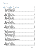 3
3 -
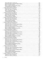 4
4 -
 5
5 -
 6
6 -
 7
7 -
8
-
9
-
10
-
11
-
12
-
13
-
14
-
15
-
16
-
17
-
18
-
19
-
20
-
21
-
22
-
23
-
24
-
25
-
26
-
27
-
28
-
29
-
30
-
31
-
32
-
33
-
34
-
35
-
36
-
37
-
38
-
39
-
40
-
41
-
42
-
43
-
44
-
45
-
46
-
47
-
48
-
49
-
50
-
51
-
52
-
53
-
54
-
55
-
56
-
57
-
58
-
59
-
60
-
61
-
62
-
63
-
64
-
65
-
66
-
67
-
68
-
69
-
70
-
71
-
72
-
73
-
74
-
75
-
76
-
77
-
78
-
79
-
80
-
81
-
82
-
83
-
84
-
85
-
86
-
87
-
88
-
89
-
90
-
91
-
92
-
93
-
94
-
95
-
96
-
97
-
98
-
99
-
100
-
101
-
102
-
103
-
104
-
105
-
106
-
107
-
108
-
109
-
110
-
111
-
112
-
113
-
114
-
115
-
116
-
117
-
118
-
119
-
120
-
121
-
122
-
123
-
124
-
125
-
126
-
127
-
128
-
129
-
130
-
131
-
132
-
133
-
134
-
135
-
136
-
137
-
138
-
139
-
140
-
141
-
142
-
143
-
144
-
145
-
146
-
147
-
148
-
149
-
150
-
151
-
152
-
153
-
154
-
155
-
156
-
157
-
158
-
159
-
160
-
161
-
162
-
163
-
164
-
165
-
166
-
167
-
168
-
169
-
170
-
171
-
172
-
173
-
174
-
175
-
176
-
177
-
178
-
179
-
180
-
181
-
182
-
183
-
184
-
185
-
186
-
187
-
188
-
189
-
190
-
191
-
192
-
193
-
194
-
195
-
196
-
197
-
198
-
199
-
200
-
201
-
202
-
203
-
204
-
205
-
206
-
207
-
208
-
209
-
210
-
211
-
212
-
213
-
214
-
215
-
216
-
217
-
218
-
219
-
220
-
221
-
222
-
223
-
224
-
225
-
226
-
227
-
228
-
229
-
230
-
231
-
232
-
233
-
234
-
235
-
236
-
237
 |
 |

HP 3PAR StoreServ 7000/7450 Storage
Cabling Configuration Guide F:
4 Node Systems with Mixed-Size Drive Enclosures
Abstract
This guide provides cabling information for authorized technicians performing installation and maintenance services on the HP
3PAR StoreServ 7000/7450 Storage systems.
HP Part Number: QR482-96429
Published: June 2013