HP 4400 HP Controller Enclosure Power Supply Replacement Instructions (593096-
HP 4400 Manual
 |
View all HP 4400 manuals
Add to My Manuals
Save this manual to your list of manuals |
HP 4400 manual content summary:
- HP 4400 | HP Controller Enclosure Power Supply Replacement Instructions (593096- - Page 1
HP Controller Enclosure Power Supply Replacement Instructions About this document For the latest documentation, go to http://www.hp.com/support/ manuals, and select your product. The information contained herein is subject to change without notice. The only warranties for HP products and services - HP 4400 | HP Controller Enclosure Power Supply Replacement Instructions (593096- - Page 2
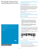
• Check status using HP P6000 Command View: 1. In the navigation pane, select Storage system > Hardware > Controller Enclosure. 2. In the Controller Enclosure Properties window, select the Power tab. The status is displayed in the Power Supplies section. An operational state of (Failed) would
-
 1
1 -
 2
2
 |
 |
HP Controller Enclosure Power
Supply Replacement Instructions
© Copyright 2008 Hewlett-Packard Development Company, L.P.
Second edition: May 2011
The information in this document is subject to change without notice.
Printed in Puerto Rico
www.hp.com
*593096-001*
About this document
For the latest documentation, go to
h
t
tp://w
w
w
.hp
.co
m/su
ppo
r
t/
man
uals
, and select your product.
The information contained herein is subject to change without notice.
The only warranties for HP products and services are set forth in the
express warranty statements accompanying such products and services.
Nothing herein should be construed as constituting an additional
warranty. HP shall not be liable for technical or editorial errors or
omissions contained herein.
WARRANTY STATEMENT:
To obtain a copy of the warranty for this product, see the warranty
information website:
h
t
tp://w
w
w
.hp
.co
m/go/s
t
o
r
age
w
ar
r
an
t
y
Before you begin
Observe the following precautions when replacing a power supply.
CAUTION:
Removing a power supply significantly changes the air flow
within the enclosure. Both power supplies must be installed for
the enclosure to cool properly. If a power supply fails, leave it
in place in the enclosure until a new power supply is available
to install.
Parts can be damaged by electrostatic discharge. Use proper
anti-static protection. Refer to the documentation that shipped
with your system for additional information.
•
Port-colored (purple) latches on components like the power supply
means the component is hot-swappable. The power supply can be
removed and replaced without having to power the system down.
•
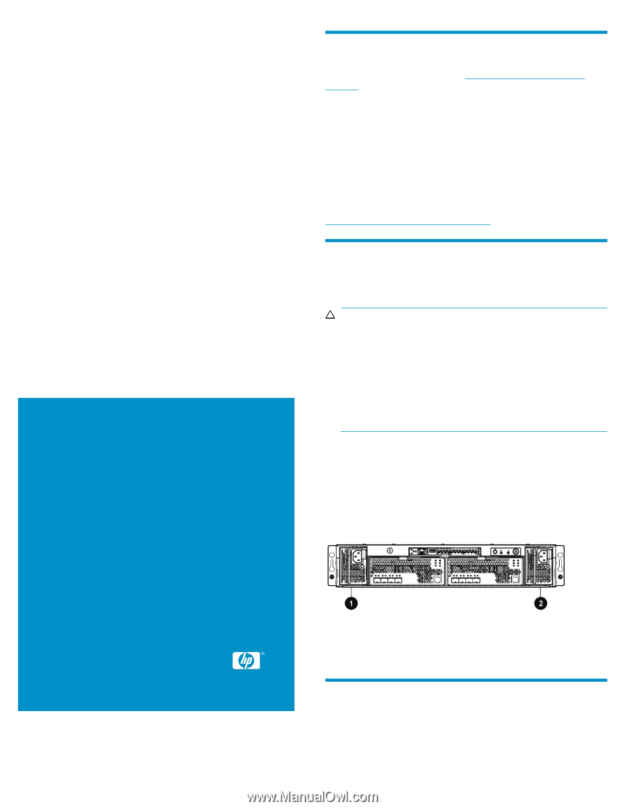
There are two power supplies at the rear of the controller enclosure.
See
Figure 1
for the locations.
•
Your controller enclosure model may vary slightly from what is illus-
trated in this document.
2. Power supply 2 (PS2)
1. Power supply 1 (PS1)
Figure 1 Power supply locations
.
Verifying component failure
Use the following methods to verify component failure:
•
Analyze any failure messages received. HP Insight Remote Support
Software provides a recommended fault monitoring.
Page 1