HP 530 HP 530 Notebook PC - Maintenance and Service Guide - Page 61
in the base enclosure.
 |
View all HP 530 manuals
Add to My Manuals
Save this manual to your list of manuals |
Page 61 highlights
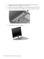
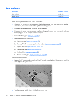
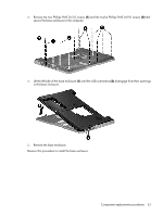
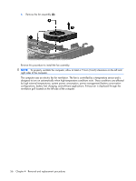
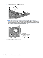
3. Remove the two Phillips PM2.0×3.0 screws (1) and the twelve Phillips PM2.0×9.0 screws (2) that secure the base enclosure to the computer. 4. Lift the left side of the base enclosure (1) until the USB connectors (2) disengage from their openings in the base enclosure. 5. Remove the base enclosure. Reverse this procedure to install the base enclosure. Component replacement procedures 53
-
 1
1 -
2
-
3
-
4
-
5
-
6
-
7
-
8
-
9
-
10
-
11
-
12
-
13
-
14
-
15
-
16
-
17
-
18
-
19
-
20
-
21
-
22
-
23
-
24
-
25
-
26
-
27
-
28
-
29
-
30
-
31
-
32
-
33
-
34
-
35
-
36
-
37
-
38
-
39
-
40
-
41
-
42
-
43
-
44
-
45
-
46
-
47
-
48
-
49
-
50
-
51
-
52
-
53
-
54
-
55
-
 56
56 -
 57
57 -
 58
58 -
 59
59 -
 60
60 -
 61
61 -
 62
62 -
 63
63 -
 64
64 -
 65
65 -
 66
66 -
67
-
68
-
69
-
70
-
71
-
72
-
73
-
74
-
75
-
76
-
77
-
78
-
79
-
80
-
81
-
82
-
83
-
84
-
85
-
86
-
87
-
88
-
89
-
90
-
91
-
92
-
93
-
94
-
95
-
96
-
97
-
98
-
99
-
100
-
101
-
102
-
103
-
104
-
105
-
106
-
107
-
108
-
109
-
110
-
111
-
112
-
113
-
114
-
115
-
116
-
117
-
118
-
119
-
120
-
121
-
122
-
123
-
124
-
125
-
126
-
127
-
128
-
129
-
130
-
131
-
132
-
133
-
134
-
135
-
136
-
137
-
138
 |
 |

3
.
Remove the two Phillips PM2.0×3.0 screws
(1)
and the twelve Phillips PM2.0×9.0 screws
(2)
that
secure the base enclosure to the computer.
4
.
Lift the left side of the base enclosure
(1)
until the USB connectors
(2)
disengage from their openings
in the base enclosure.
5
.
Remove the base enclosure.
Reverse this procedure to install the base enclosure.
Component replacement procedures
53