HP 530 HP 530 Notebook PC - Maintenance and Service Guide - Page 63
Fan assembly, Display assembly see
 |
View all HP 530 manuals
Add to My Manuals
Save this manual to your list of manuals |
Page 63 highlights
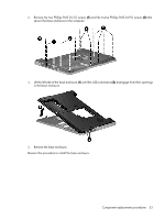
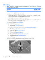
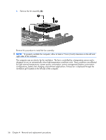
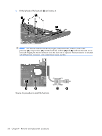
Reverse this procedure to install the RTC battery. Be sure the RTC battery is installed with the "+" sign facing up. Fan assembly Description Fan assembly Spare part number 438528-001 Before removing the fan assembly, follow these steps: 1. Shut down the computer. If you are unsure whether the computer is off or in Hibernation, turn the computer on, and then shut it down through the operating system. 2. Disconnect all external devices connected to the computer. 3. Disconnect the power from the computer by first unplugging the power cord from the AC outlet and then unplugging the AC adapter from the computer. 4. Remove the battery (see Battery on page 32). 5. Remove the following components: a. Hard drive (see Hard drive on page 33) b. Memory/WLAN module compartment cover (see Memory module on page 35) c. Optical drive (see Optical drive on page 39) d. Switch cover (see Switch cover on page 41) e. Keyboard (see Keyboard on page 43) f. Display assembly (see Display assembly on page 47) g. Base enclosure (see Base enclosure on page 52) Remove the fan assembly: 1. Disconnect the fan cable (1) from the system board. 2. Remove the Phillips PM2.0×9.0 screw (2) that secures the fan assembly to the top cover. Component replacement procedures 55
-
 1
1 -
2
-
3
-
4
-
5
-
6
-
7
-
8
-
9
-
10
-
11
-
12
-
13
-
14
-
15
-
16
-
17
-
18
-
19
-
20
-
21
-
22
-
23
-
24
-
25
-
26
-
27
-
28
-
29
-
30
-
31
-
32
-
33
-
34
-
35
-
36
-
37
-
38
-
39
-
40
-
41
-
42
-
43
-
44
-
45
-
46
-
47
-
48
-
49
-
50
-
51
-
52
-
53
-
54
-
55
-
56
-
57
-
 58
58 -
 59
59 -
 60
60 -
 61
61 -
 62
62 -
 63
63 -
 64
64 -
 65
65 -
 66
66 -
 67
67 -
 68
68 -
69
-
70
-
71
-
72
-
73
-
74
-
75
-
76
-
77
-
78
-
79
-
80
-
81
-
82
-
83
-
84
-
85
-
86
-
87
-
88
-
89
-
90
-
91
-
92
-
93
-
94
-
95
-
96
-
97
-
98
-
99
-
100
-
101
-
102
-
103
-
104
-
105
-
106
-
107
-
108
-
109
-
110
-
111
-
112
-
113
-
114
-
115
-
116
-
117
-
118
-
119
-
120
-
121
-
122
-
123
-
124
-
125
-
126
-
127
-
128
-
129
-
130
-
131
-
132
-
133
-
134
-
135
-
136
-
137
-
138
 |
 |