HP 6400/8400 HP StorageWorks controller enclosure replacement instructions (51
HP 6400/8400 Manual
 |
View all HP 6400/8400 manuals
Add to My Manuals
Save this manual to your list of manuals |
HP 6400/8400 manual content summary:
- HP 6400/8400 | HP StorageWorks controller enclosure replacement instructions (51 - Page 1
of the warranty for this product, see the warranty information website: http://www.hp.com/go/storagewarranty These instructions apply to the EVA6400/8400 product family. Before you begin Observe the following precautions when replacing a controller. CAUTION: Parts can be damaged by electrostatic - HP 6400/8400 | HP StorageWorks controller enclosure replacement instructions (51 - Page 2
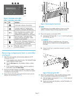
more battery units have failed. 6 Blue LED used to identify a specific controller enclosure. Removing components from a controller enclosure 1. Halt I/O to the controller enclosure being replaced with HP Command View EVA: a. In the navigation pane, select the array. The Initialized Storage System - HP 6400/8400 | HP StorageWorks controller enclosure replacement instructions (51 - Page 3
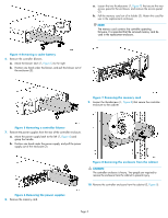
card be used in the replacement enclosure. Figure 4 Removing a cache battery 6. Remove the controller blowers. a. Move the blower controller enclosure to the cabinet. Figure 5 Removing a controller blower 7. Remove the power supplies from the rear of the controller enclosure. a. Move the power - HP 6400/8400 | HP StorageWorks controller enclosure replacement instructions (51 - Page 4
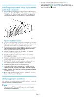
above the OCP. Record the product number and serial number from the controller being replaced onto the replacement controller label to ensure the continuation of service entitlement. • Verify the controller health green LED is lit (see Table 1). • From HP Command View EVA, navigate to the component
-
 1
1 -
 2
2 -
 3
3 -
 4
4
 |
 |
HP StorageWorks
controller enclosure replacement
instructions
These instructions apply to the EVA6400/8400
product family.
© Copyright 2009 Hewlett-Packard Development Company, L.P.
First edition: March 2009
The information in this document is subject to change without
notice.
Printed in Puerto Rico
www.hp.com
*514016-001*
About this document
This document provides the procedure for replacing an HSV400 or
HSV450 controller enclosure. For the latest documentation, go to
h
t
t
p
:
/
/
w
w
w
.
h
p
.
c
o
m
/
s
u
p
p
o
r
t
/
m
a
n
u
a
l
s
, and select your product.
The information contained herein is subject to change without notice.
The only warranties for HP products and services are set forth in the
express warranty statements accompanying such products and services.
Nothing herein should be construed as constituting an additional
warranty. HP shall not be liable for technical or editorial errors or
omissions contained herein.
WARRANTY STATEMENT: To obtain a copy of the warranty for this
product, see the warranty information website:
h
t
t
p
:
/
/
w
w
w
.
h
p
.
c
o
m
/
g
o
/
s
t
o
r
a
g
e
w
a
r
r
a
n
t
y
Before you begin
Observe the following precautions when replacing a controller.
CAUTION:
Parts can be damaged by electrostatic discharge. Use proper
anti-static protection. Refer to the documentation that shipped
with your system for additional information.
Verifying component failure
Use the following methods to verify component failure:
•
Analyze any failure messages received. Fault monitoring software
from HP (WEBES) provides a recommended solution.
•
Check status using HP Command View EVA:
1.
In the navigation pane, select
Storage system > Hardware >
Controller Enclosure > Controller
.
2.
The status is displayed in the Operational State
fi
eld. An
operational state of
(Failed) would indicate a fault that may
require a replacement.
3.
To help identify the correct controller, click
Locate > Locate On
.
This causes the blue UID indicator to light at the front and rear
of the controller enclosure.
•
Check the controller enclosure status LEDs as shown in
Figure 1
and
Table 1
.
Page 1