HP 6400/8400 HP StorageWorks disk enclosure midplane replacement instructions
HP 6400/8400 Manual
 |
View all HP 6400/8400 manuals
Add to My Manuals
Save this manual to your list of manuals |
HP 6400/8400 manual content summary:
- HP 6400/8400 | HP StorageWorks disk enclosure midplane replacement instructions - Page 1
disk enclosure midplane replacement instructions About this document For the latest documentation, go to http://www.hp.com/support/ manuals, and select your product. The information contained herein is subject to change without notice. The only warranties for HP products and services are set forth - HP 6400/8400 | HP StorageWorks disk enclosure midplane replacement instructions - Page 2
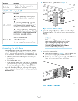
nl nl Amber = Fault condition. nl nl Off = Fan unseated from connector or failed. Removing the midplane 1. Power down the array. For the EVA, use HP Command View EVA or, on the EVA4400 only, the Web-based operator control panel (WOCP). Powering down the controllers also removes power from the disk - HP 6400/8400 | HP StorageWorks disk enclosure midplane replacement instructions - Page 3
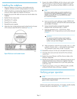
6. Remove both fan modules. a. Push up on the mounting latch (1, Figure 3) and pull the fan slightly out of the enclosure (2). b. Position one hand under the fan, and with the other hand, pull the fan out of the enclosure. 8. Remove the top access cover. a. Lift the access panel latch (1, Figure - HP 6400/8400 | HP StorageWorks disk enclosure midplane replacement instructions - Page 4
to an unprogrammed midplane EEPROM that resides on a spare midplane provided by HP. Once the EEPROM has been set, it cannot be changed. a. Insert one end of a serial cable (part number 259992-001) into a laptop serial port, and insert the other end into the serial port of either I/O
-
 1
1 -
 2
2 -
 3
3 -
 4
4
 |
 |

HP StorageWorks
disk enclosure midplane
replacement instructions
These instructions apply to the MSA6X/7X, Proliant
DL320S, EVA4400, EVA6400, and EVA8400 product
families.
© Copyright 2009 Hewlett-Packard Development Company, L.P.
Second edition: February 2009
The information in this document is subject to change without notice.
Printed in Puerto Rico
www.hp.com
*533480-001*
About this document
For the latest documentation, go to
h
t
tp://w
w
w
.hp
.co
m/su
ppo
r
t/
man
uals
, and select your product.
The information contained herein is subject to change without notice.
The only warranties for HP products and services are set forth in the
express warranty statements accompanying such products and services.
Nothing herein should be construed as constituting an additional
warranty. HP shall not be liable for technical or editorial errors or
omissions contained herein.
WARRANTY STATEMENT: To obtain a copy of the warranty for this
product, see the warranty information website:
h
t
tp://w
w
w
.hp
.co
m/
go/s
t
o
r
age
w
ar
r
an
t
y
Before you begin
This procedure requires that the EEPROM on the midplane board be
programmed with the product salable serial number. You will need a
PC or laptop with a serial port, a terminal emulation program, and the
serial cable (part number 259992–001) provided with the midplane
spare kit.
Observe the following precautions when replacing the midplane.
CAUTION:
Parts can be damaged by electrostatic discharge. Use proper
anti-static protection. Refer to the documentation that shipped
with your system for additional information.
Slate blue-colored items, such as the midplane thumbscrews,
means their attached component is not hot-swappable. Power
to the disk enclosure must be shut down before the component
is removed.
Verifying component failure
Before replacing the midplane, verify its failure by checking the LED
status of the following components:
•
Disk drives—Test with a known good disk drive (see
Table 1
).
•
I/O module—Test with a known good I/O module (see
Table 2
).
•
Fan module—Test with a known good fan module (see
Table 2
).
Table 1 Drive status LEDs
Description
Drive LED
•
Flashing—Drive is spinning up or down and
is not ready.
•
Solid—Drive is ready to perform I/O opera-
tions.
•
Flickering—Indicates drive activity.
Green (bottom)
Page 1