HP 6400/8400 HP StorageWorks disk enclosure midplane replacement instructions - Page 3
Removing an I/O module
 |
View all HP 6400/8400 manuals
Add to My Manuals
Save this manual to your list of manuals |
Page 3 highlights
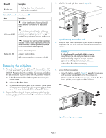
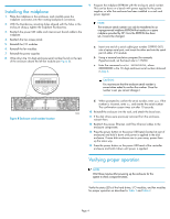
6. Remove both fan modules. a. Push up on the mounting latch (1, Figure 3) and pull the fan slightly out of the enclosure (2). b. Position one hand under the fan, and with the other hand, pull the fan out of the enclosure. 8. Remove the top access cover. a. Lift the access panel latch (1, Figure 5). The access panel will slightly disengage from the enclosure. b. Slide the access panel to the rear (2). 1 2 2 1 15802 Figure 3 Removing a fan module 7. Remove both I/O modules. a. Pull the mounting latch down (1, Figure 4) and pull the modules slightly out of the enclosure (2). b. Position one hand under the I/O module, and with the other hand, pull the module out of the enclosure. 15818 Figure 5 Removing top access cover 9. Remove the power UID cable (1, Figure 6) and interconnect board cable (2) where they attach to the midplane board. 1 2 15814 Figure 6 Removing midplane cabling 2 10. Loosen the two midplane thumbscrews (1, Figure 7). 1 Figure 4 Removing an I/O module 15804 3 1 2 15813 Figure 7 Removing the midplane 11. Push the midplane toward the back of the unit to disengage it from the backplane (2). 12. Tilt the midplane up and remove it from the enclosure (3). Page 3
-
 1
1 -
 2
2 -
 3
3 -
 4
4
 |
 |
