HP 6400/8400 HP StorageWorks disk enclosure midplane replacement instructions - Page 4
Installing the midplane, Verifying proper operation
 |
View all HP 6400/8400 manuals
Add to My Manuals
Save this manual to your list of manuals |
Page 4 highlights
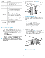
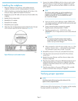
Installing the midplane 1. Place the midplane in the enclosure, and carefully press the midplane connectors into their mating backplane connectors. 2. With the thumbscrew mounting holes aligned with the holes in the enclosure chassis, tighten the midplane thumbscrews. 3. Reattach the power UID cable and interconnect board cable to the midplane. 4. Reattach the top access panel. 5. Reinstall the I/O modules. 6. Reinstall the fan modules. 7. Reinstall the power supplies 8. Write down the 10-digit enclosure serial number found on the rear of the enclosure above the left fan module (see Figure 8). Product Number: AG638A Serial Number: xxxxxxxxxxx 9. Program the midplane EEPROM with the enclosure serial number. This can be done on a bench with power applied to the power supplies, or after the enclosure has been installed in a rack and power applied. NOTE: The enclosure serial number can only be transferred to an unprogrammed midplane EEPROM that resides on a spare midplane provided by HP. Once the EEPROM has been set, it cannot be changed. a. Insert one end of a serial cable (part number 259992-001) into a laptop serial port, and insert the other end into the serial port of either I/O module. b. Using a terminal emulation program (for example, HyperTerminal), set the baud rate to 115200. c. Enter the command ssnSet XXXXXXXXXX, where XXXXXXXXXX is the 10-digit enclosure serial number obtained in Step 8. CAUTION: You must ensure that the enclosure serial number is correct when asked to confirm the number. Once the number is set, you cannot change it. Product Number: AG638A Serial Number: xxxxxxxxxxx Figure 8 Enclosure serial number location d. When prompted to confirm the serial number, enter yes. If the number is incorrect, enter no, and reenter the serial number. The confirmation screen times out after 10 seconds. 15822 10. Reinstall the enclosure into the rack, and attach the bezel ears. 11. If the disk drives were previously removed from the enclosure, reinsert them. 12. Reattach the power, Ethernet, and Fibre Channel cables to the enclosure components. 13. Press the power button on the power UID bezel (located at rear of enclosure) and hold it down until power is applied to the disk enclosure. If more disk enclosures are in your array, power them up the same way. 14. Press the power button on the power UID bezel of the controller enclosure and hold it down until power is applied. Verifying proper operation NOTE: Wait three minutes after powering up the enclosure for the system to check component status. Verify the status LEDs of the hard drives, I/O modules, and fan modules for proper operation as described in Table 1 and Table 2. Page 4
-
 1
1 -
 2
2 -
 3
3 -
 4
4
 |
 |
