HP 8/20q HP StorageWorks 8/20q Fibre Channel Switch Rack Mount Kit quick start - Page 2
Collect the required items, Verify the kit contents, Rack the switch
 |
View all HP 8/20q manuals
Add to My Manuals
Save this manual to your list of manuals |
Page 2 highlights
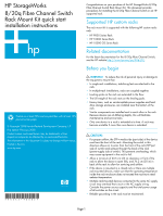
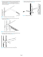
Collect the required items NOTE: The rack mount kit installation requires one technician. Locate the following items and set them aside: • 8/20q Fibre Channel Switch • 8/20q Fibre Channel Switch rack mount kit Smaller items, such as screws, ship in plastic bags in the kit. See Table 1. Required tools: • #2 Phillips screwdriver • 7/16-inch wrench Verify the kit contents Check the contents of the 8/20q Fibre Channel Switch rack mount kit shipping carton to verify that all required parts and hardware are available (Table 1). Table 1 8/20q Fibre Channel Switch rack mount kit hardware Item Description Two (2) rear mounting brackets Table 1 8/20q Fibre Channel Switch rack mount kit hardware Item Description Two (2) 1/4-20 hex nuts with lock washers Two (2) 1/4-inch flat washers Rack the switch 1. Remove and discard the four 10-32 screws from the sides of the switch. 2. Attach each rail to the switch using two 10-32 x .375-inch screws with captive washers (Figure 1). Make sure the slotted ends of the rails are on the power-supply side (not the SFP-port side) of the switch. Two (2) switch rails One (1) filler panel (optional), see step 7. Ten (10) M6 machine screws Ten (10) M6 cage-nuts for square rack holes Figure 1 Attaching the rails to the switch 3. On the rack vertical posts, mark the holes that will be used by the rail flanges (three on each rear vertical post, two on each front vertical post). Then, from the inside of each vertical post, insert an M6 cage-nut for the rack you are using (square or round hole) into each marked hole (Figure 2). Fasten each rear mounting bracket to the marked holes, using two M6 machine screws. Ten (10) M6 cage-nuts for round rack holes Four (4) 10-32 x .375-inch screws with captive washers Figure 2 Installing the rear mounting brackets Page 2
-
 1
1 -
 2
2 -
 3
3
 |
 |
