HP A3550A Battery Backup Unit Installation Guide (10 and 30 Slot Disk Arrays)
HP A3550A - High Availability Disk Arrays Model 20 Storage Enclosure Manual
 |
View all HP A3550A manuals
Add to My Manuals
Save this manual to your list of manuals |
HP A3550A manual content summary:
- HP A3550A | Battery Backup Unit Installation Guide (10 and 30 Slot Disk Arrays) - Page 1
Hewlett-Packard Battery Backup Unit (BBU) Installation Guide (10 and 30-slot Disk Arrays) Hewlett-Packard BBUs are customer installable and replaceable. A replacement BBU must be the same type as the BBU being - HP A3550A | Battery Backup Unit Installation Guide (10 and 30 Slot Disk Arrays) - Page 2
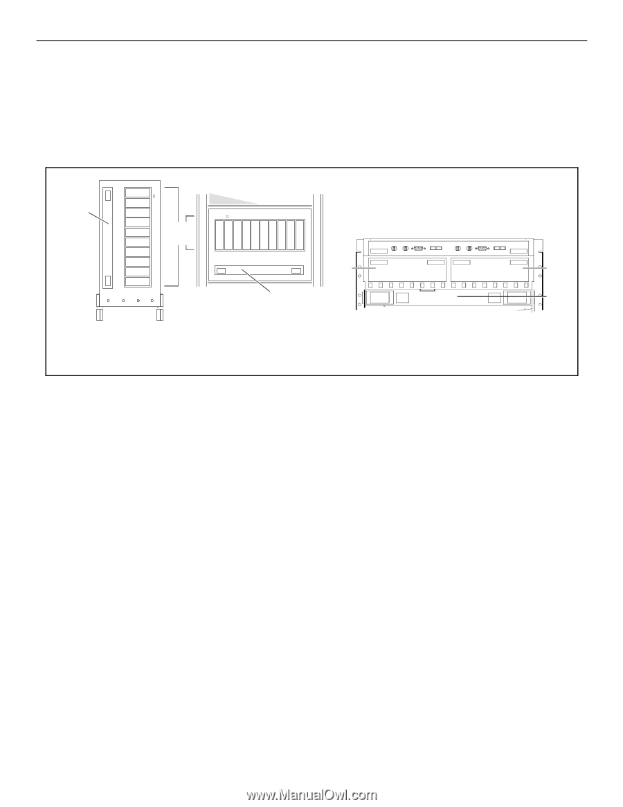
, it cannot be opened without using the release button. For more information on BBU installation procedures and recharge times, see the disk array user guide. deskside 10-slot disk array rackmount 10-slot disk array Figure 2. 30-slot disk array, rackmount only (fan pack not shown for clarity
-
 1
1 -
 2
2
 |
 |
Hewlett-Packard Battery Backup Unit (BBU)
Installation Guide (10 and 30-slot Disk Arrays)
Hewlett-Packard BBUs are customer installable and replaceable. A replacement BBU must be the same type as the BBU
being replaced.
The locations of the BBUs in the 10-slot and 30-slot disk arrays are shown in Figure 1.
.
Figure 1.
Install or replace a BBU by performing the following steps. Place a check in the appropriate
o
as the step is completed.
Step 1:
Observe antistatic precautions
A BBU is shipped with an ESD kit containing:
–
ESD wrist strap
–
ESD conductive sheet
o
Ground the ESD wrist strap to any unplated metal on
the disk array chassis and fasten the strap to your wrist.
On 30-slot disk arrays, ground the ESD wrist strap to
the metal edge above the rear retaining screws.
On 10-slot disk arrays, ground the ESD wrist strap to
the metal edge around the disk modules.
Step 2:
Prepare to install the BBU
o
Remove the new BBU from its shipping carton and
place it on a suitable antistatic surface or the ESD con-
ductive sheet.
o
If installing a BBU in a 10-slot disk array, remove the
front bezel by pulling it off on one side and then the
other.
o
If installing a BBU in a 30-slot disk array, open the fan
pack by pressing the release button and carefully swing-
ing the fan pack open.
The BBU can be installed or replaced with array power on.
For the 30-slot array, the installation or replacement
MUST
be completed and the fan pack closed within two minutes to
avoid a thermal shutdown.
Battery
backup unit
(BBU)
disk-drive
modules
Front view of 10-slot
deskside disk array
(front bezel removed for clarity)
Battery
backup unit
(BBU)
Front view of 10-slot
rackmount disk array
(front bezel removed for clarity)
SP-A
SP-B
BBU
Rear view, top of a 30-slot disk array, rackmount only
(fan pack not shown for clarity)