HP A3550A Battery Backup Unit Installation Guide (10 and 30 Slot Disk Arrays) - Page 1
HP A3550A - High Availability Disk Arrays Model 20 Storage Enclosure Manual
 |
View all HP A3550A manuals
Add to My Manuals
Save this manual to your list of manuals |
Page 1 highlights
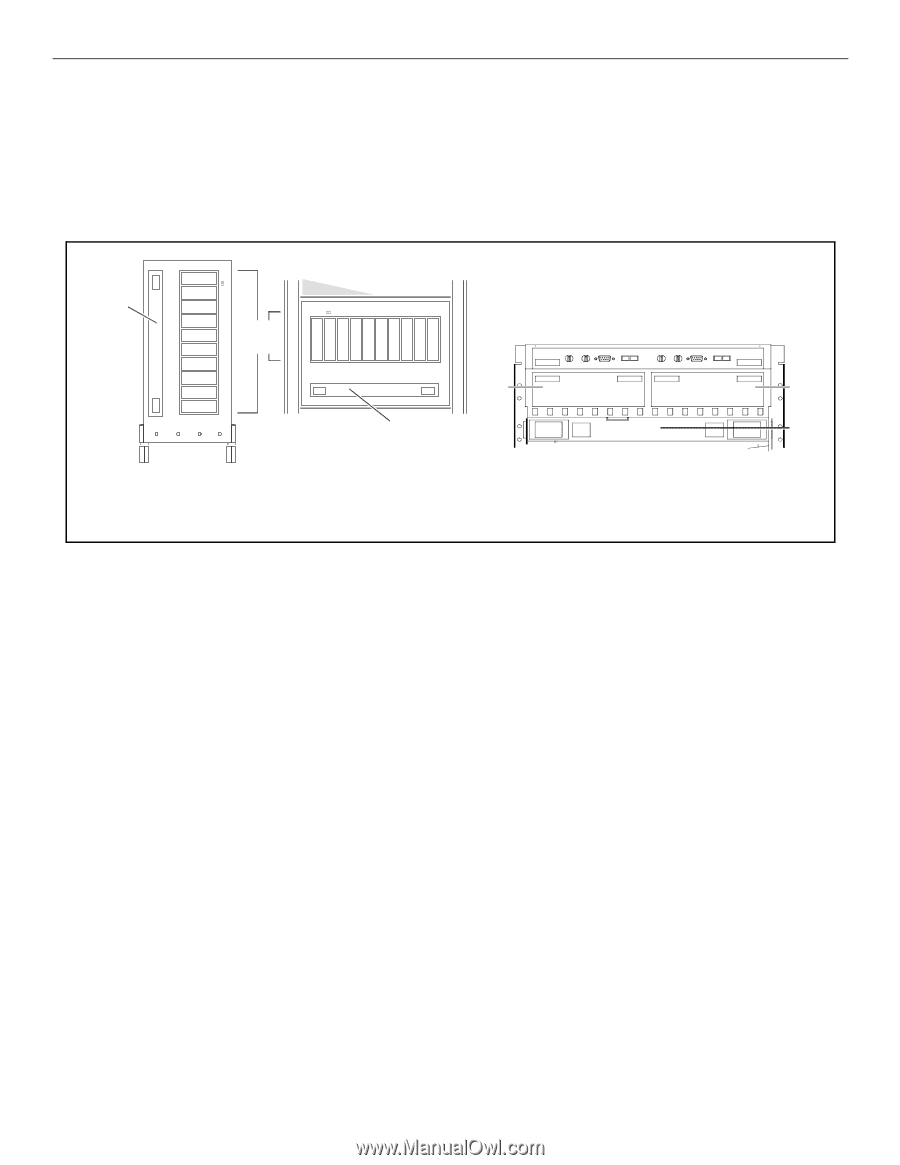
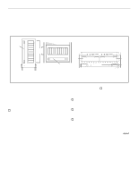
Hewlett-Packard Battery Backup Unit (BBU) Installation Guide (10 and 30-slot Disk Arrays) Hewlett-Packard BBUs are customer installable and replaceable. A replacement BBU must be the same type as the BBU being replaced. The locations of the BBUs in the 10-slot and 30-slot disk arrays are shown in Figure 1. . Battery backup unit (BBU) disk-drive modules Front view of 10-slot deskside disk array (front bezel removed for clarity) Battery backup unit (BBU) Front view of 10-slot rackmount disk array (front bezel removed for clarity) SP-A SP-B BBU Rear view, top of a 30-slot disk array, rackmount only (fan pack not shown for clarity) Figure 1. Install or replace a BBU by performing the following steps. Place a check in the appropriate o as the step is completed. Step 1: Observe antistatic precautions A BBU is shipped with an ESD kit containing: - ESD wrist strap - ESD conductive sheet o Ground the ESD wrist strap to any unplated metal on the disk array chassis and fasten the strap to your wrist. On 30-slot disk arrays, ground the ESD wrist strap to the metal edge above the rear retaining screws. On 10-slot disk arrays, ground the ESD wrist strap to the metal edge around the disk modules. Step 2: Prepare to install the BBU o Remove the new BBU from its shipping carton and place it on a suitable antistatic surface or the ESD conductive sheet. o If installing a BBU in a 10-slot disk array, remove the front bezel by pulling it off on one side and then the other. o If installing a BBU in a 30-slot disk array, open the fan pack by pressing the release button and carefully swinging the fan pack open. The BBU can be installed or replaced with array power on. For the 30-slot array, the installation or replacement MUST be completed and the fan pack closed within two minutes to avoid a thermal shutdown.
-
 1
1 -
 2
2
 |
 |