HP A3550A Storage Processor (SP) Installation Guide - Not Orderable - Page 1
HP A3550A - High Availability Disk Arrays Model 20 Storage Enclosure Manual
 |
View all HP A3550A manuals
Add to My Manuals
Save this manual to your list of manuals |
Page 1 highlights
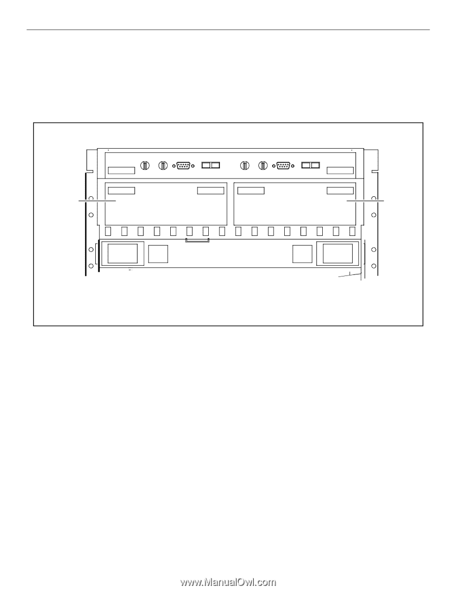
Hewlett-Packard Storage Processor (SP) Installation Guide Hewlett-Packard SPs are customer installable and replaceable. A replacement SP must be the same type as the SP being replaced. The locations of the SPs in the 30-slot disk arrays are shown in Figure 1. . SP-A SP-B Rear view, top of the disk array Figure 1. Install an SP by performing the following steps. Place a check in the appropriate o as the step is completed. Step 1: Observe antistatic precautions An SP is shipped with an ESD kit containing: - ESD wrist strap - ESD conductive sheet o Ground the ESD wrist strap to the metal edge above the rear retaining screws and fasten the strap to your wrist. Step 2: Prepare to install the SP o Remove the replacement SP from its shipping carton and place it on a suitable antistatic work surface or the ESD conductive sheet. Array power can be left on during SP removal and replacement. o Remove the failed SP. o Remove the memory modules from the failed SP. o Insert memory modules in the SIMM connectors on the SP to be installed. See the 2EMOVAL AND 2EPLACEMENT chapter in the (EWLETT 0ACKARD (IGH !VAILABILITY &IBRE #HANNEL $ISK !RRAY 5SER 'UIDE for more information about SIMM removal and replacement.
-
 1
1 -
 2
2
 |
 |