HP AD510A HP StorageWorks Modular Smart Array 1500 cs Configuration Overview ( - Page 4
MSA1500 cs Installation and Configuration Best Practices - power
 |
UPC - 829160218625
View all HP AD510A manuals
Add to My Manuals
Save this manual to your list of manuals |
Page 4 highlights
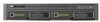
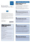
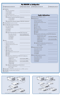
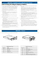
MSA1500 cs Installation and Configuration Best Practices Consider the following when installing and configuring your MSA1500 cs: ● Use the Configuration Planning Worksheet on the opposite side of this poster to help you gather all of the items required for installing your MSA1500 cs. ● Go to the MSA1500 cs web site at http://www.hp.com/go/msa1500cs to confirm your plans and review current information about the MSA1500 cs. ● Record infomation about your system on the provided worksheets on the opposite side of this poster or in the installation guide. ● Install your MSA1500 cs in the sequence listed in this poster and in the installation guide. Several installation and configuration steps include dependencies; if you deviate from the listed sequence, you may have to un-install and then re-install your MSA1500 cs . ● Use the HP StorageWorks MSA1500 cs Installation Guide to install and configure your MSA1500 cs. Details are available in the guide that are not provided in this Overview. ● When planning your arrays: - Customize the RAID level and striping method to the type of data that will be stored on the array. - Set the drive rebuild priority of the array to "high" to minimize exposure during a drive failure. - Optimize performance and redundancy by striping the drives in the array across separate storage enclosures on different SCSI buses, especially in mirrored environments using RAID 1 or RAID 1+0. Note: Depending on the number of drives included in an array, the ACU automatically assumes a default RAID type of ADG, which maximizes fault tolerance and storage efficiency, but at a significant cost of I/O performance. For comparable fault tolerance but higher performance, consider using RAID 1+0. ● If your environment includes multiple-servers, consider designating one of the servers as a management server to centralize your management tasks. It is on this server that you install management software such as the ACU and perform SAN management tasks. ● Before installing your MSA1500 cs, consider redundancies of power, storage, and data paths. To provide redundant power, be sure to plug the two power supplies on the MSA1500 cs into separate Uninterruptable Power Supplies (UPS) on separate power sources. If you have only one UPS, maintain separate power paths by plugging one MSA1500 cs power supply to the UPS on one power source and the other MSA1500 cs power supply to a separate power source. To provide redundant storage, configure your arrays using fault-tolerant RAID levels and striping methods. To provide redundant data paths, you must include two isolated Fibre Channel fabrics and the associated hardware and software components in the configuration. (For example, you must include two controllers, two interconnect devices, and two HBAs in each server. Environments using Secure Path and the ACU must have the software installed on each server.) ● When installing or updating the HBA drivers, always use the drivers and the installation scripts provided on the MSA1500 cs Support Software CD or the MSA1500 cs web site. Your MSA1500 cs will not operate as intended if you update your HBA driver manually or use drivers obtained from the HBA manufacturer. ● After configuring the storage, remember to: - Identify the operating system of each HBA with access to the storage. - Verify that each HBA in each server has been granted access to the storage. - Control access to the storage by indicating which HBA can access which array. ● If you are installing the MSA1500 cs in a multi-path environment that requires Secure Path software, be sure to follow every server reboot prompt. Failure to acknowledge a server reboot may result in your path redundancy not functioning properly. Be sure to reboot your server after the copy from the source media to the server is completed and after the redundancy driver is attached to the arrays. MSA1500 cs Features Two views of the MSA1500 cs are shown, with the key components identified. 7 6 3 2 45 1 12 345 10 9 8 76 Reference # 1 2 3 4 5 6 7 MSA1500 cs (Front View) Identifier Redundant controller slot blank Primary controller Status indicators Display panel Display push buttons Power switch Unit ID button and indicator Reference # 1 2 3 4 5 6 7 8 9 : MSA1500 cs (Rear View) Identifier Reserved for future use Primary Fibre Channel I/O module System information panel SCSI I/O module, bus 0 Power supplies Additional SCSI I/O module slot, bus 1 Redundant Fibre Channel I/O module slot Fan modules Additional SCSI I/O module slots, buses 2 and 3 2-Gb Small Form Factor Pluggable (SFP) Transceiver
-
 1
1 -
 2
2 -
 3
3 -
 4
4
 |
 |
