HP AD510A HP StorageWorks 1500/1510i Modular Smart Array chassis replacement i - Page 2
Removing the failed chassis
 |
UPC - 829160218625
View all HP AD510A manuals
Add to My Manuals
Save this manual to your list of manuals |
Page 2 highlights
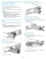
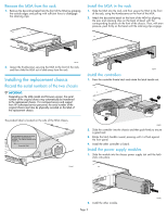
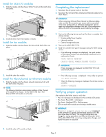
Removing the failed chassis Prepare for the replacement 1. If the MSA is operational, stop all access to the MSA. 2. Press and hold the power on/standby button for five seconds to place the MSA in standby. 3. Label each cable carefully and then disconnect all of the cables. CAUTION: If replacing the MSA1500 chassis, use caution when handling the Fibre Channel cables: • Touching the end of a Fibre Channel cable will either damage the cable or cause performance problems, including intermittent difficulties accessing the storage. • When a Fibre Channel cable is not connected, replace the protective covers on the ends of the cable. Remove the Fibre Channel (or Ethernet) I/O modules 1. Lift the port-colored latch and pull the module out of the chassis. NOTE: The following illustration demonstrates removing a Fibre Channel I/O module from the MSA1500 chassis. For the MSA1510i, the 2-Port Ethernet iSCSI I/O module is in this slot. Remove the SCSI I/O modules 1. Lift the port-colored latch and pull the module out of the chassis. 2 1 15644 2. Remove all other SCSI I/O modules or blanks. Remove the power supply modules 1. Press the port-colored latch towards the side of the module and pull the module out of the chassis. 1 2 1 15498 2. Remove the other I/O module or blank. Remove the fan modules 1. Lift the port-colored latch and pull the module out of the chassis. 2 15645 2. Remove the other module. Remove the controllers 1. Press the controller thumb latch to release the latch handle, and then rotate the latch handle out. 2 2. Remove the other fan module. 2 1 15643 1 15492 2. Grasp the latch handle and pull the controller out of the chassis. 3. Remove the other controller or blank. Page 2
-
 1
1 -
 2
2 -
 3
3 -
 4
4 -
 5
5
 |
 |
