HP AD510A HP StorageWorks 1500/1510i Modular Smart Array chassis replacement i - Page 4
Completing the replacement, Verifying proper operation
 |
UPC - 829160218625
View all HP AD510A manuals
Add to My Manuals
Save this manual to your list of manuals |
Page 4 highlights
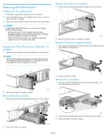
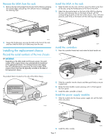
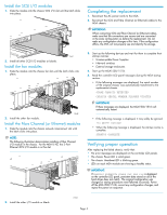
Install the SCSI I/O modules 1. Slide the module into the chassis SCSI I/O slot until the latch clicks into place. Completing the replacement 1. Reconnect the AC power cords to the MSA. 2. Reconnect the SCSI and Fibre Channel (or Ethernet) cables to the MSA chassis. IMPORTANT: When connecting SCSI and Fibre Channel (or Ethernet) cables, make sure that the connections are secure and are connected in the same configuration as before the replacement. Do not make any configuration changes at this time. If the configuration differs, the MSA will not properly see and identify the storage. 15647 2. Install all other SCSI I/O modules or blanks. Install the fan modules 1. Slide the module into the chassis fan slot until the latch clicks into place. 15648 2. Install the other fan module. Install the Fibre Channel (or Ethernet) modules 1. Slide the module into the chassis network interconnect slot until the latch clicks into place. NOTE: The following illustration demonstrates installing a Fibre Channel I/O module in the chassis. For the MSA1510i, the 2-Port Ethernet iSCSI I/O module is in this slot. 3. Start up the following devices and wait for them to complete their startup routines: • Uninterruptible Power Supplies • Network switches • External storage enclosures 4. Start up the MSA1500/1510i. 5. Read the controller LCD panel messages during the MSA startup routine. • If the following messages are displayed, the serial number of the original chassis was automatically transferred to the replacement chassis. SPARE CHASSIS DETECTED CHASSIS SERIAL NUMBER FLASHED UPDATED IMPORTANT: If these messages are displayed, the MSA1500/1510i will automatically restart. • If the following message is displayed, it may safely be ignored. I2C WRITE FAILURE • When the following message is displayed, the startup routine is complete. STARTUP COMPLETE Verifying proper operation After replacing the failed chassis, verify that: • No error messages are displayed on the controller LCD panels. • The chassis Power LED is solid green. • The chassis Heartbeat LED is blinking green. • LEDs on each MSA module are showing a healthy status. IMPORTANT: If CHASSIS MISMATCH POWER OFF AND FIX is displayed on the controller LCD panel, persistent data stored on all of the hard drives does not match. The original configuration was changed or startup procedures were followed incorrectly. Power off the MSA1500/1510i, correct any configuration changes, and repeat the power-on sequence. 2. Install the other I/O module or blank. 15502 Page 4
-
 1
1 -
 2
2 -
 3
3 -
 4
4 -
 5
5
 |
 |
