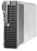
HP BL260c Electrical signal integrity considerations for HP BladeSystem - Page 6
Significant factors affecting signal integrity, Dielectric losses, Skin effect
 |
UPC - 883585668663
View all HP BL260c manuals
Add to My Manuals
Save this manual to your list of manuals |
Page 6 highlights
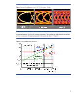
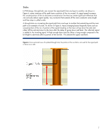
Significant factors affecting signal integrity A transmitted signal arriving at the receiver must maintain sufficient magnitude and quality to be reliably recognized. As signal frequency increases, previously inconsequential factors emerge as new obstacles. Line bandwidth is affected by attenuation introduced by factors such as dielectric loss and the skin effect. Additionally, the reflections produced at impedance discontinuities, specifically at connector interfaces, become significant because they generate noticeable signal distortion. At these speeds, crosstalk between transmission lines becomes a limiting factor. These factors are discussed briefly below. Dielectric losses Dielectric loss is caused by the electromagnetic field associated with a signal traveling along a conductor and its interaction with the adjacent material, in this case the printed circuit board. This interaction contributes to high frequency signal attenuation. Dielectric loss is a principal cause responsible for frequency-dependent losses within printed circuit boards. Skin effect The skin effect essentially increases the resistance of a conductor as the signal frequency increases. As the signal frequency increases, the signal current is forced toward the surface of the conductor by the magnetic field and to vacate the center of the conductor. The signal current is said to travel at the "skin" of the conductor. This has the effect of limiting the accessible area of the conductor that is available to carry the signal current, increasing the resistance of that conductor. Impedance discontinuities Potentially, impedance discontinuities may occur at any point where the transmitted signal is transferred from one component to another. This transfer normally represents a physical structure change in the signal path, such as, connectors, plated through-holes for connector pins, vias for transitioning printed circuit board (PCB) layers, and differing board materials. At the point of the discontinuity, an impedance change creates reflected energy back to the source of the signal. This becomes a new signal that adds to the desired signal at an incorrect time effectively reducing the quality of the transmitted signal. 6
-
 1
1 -
 2
2 -
 3
3 -
 4
4 -
 5
5 -
 6
6 -
 7
7 -
 8
8 -
 9
9 -
 10
10 -
 11
11 -
 12
12 -
13
-
14
-
15
-
16
 |
 |
