HP BL680c ProLiant BL680c Generation 5 Server Blade Installation Instructions - Page 2
Connecting to the network, Installing a server blade
 |
UPC - 884420396314
View all HP BL680c manuals
Add to My Manuals
Save this manual to your list of manuals |
Page 2 highlights
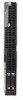
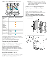
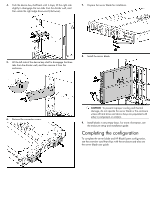
Installation is shown in the HP BladeSystem c7000 Enclosure. Server blade signal NIC 1 (Embedded) NIC 2 (Embedded) NIC 3 (Embedded) NIC 4 (Embedded) Mezzanine 1 Mezzanine 2 Mezzanine 3 Interconnect bay Interconnect bay labels 1 2 1 2 3 and 4 5 and 6 7 and 8 7 and 8 5 and 6 For detailed port mapping information, see the HP BladeSystem enclosure quick setup guide or the HP BladeSystem enclosure setup and installation guide on the HP website (http://www.hp.com/go/bladesystem/documentation). Connecting to the network To connect the HP BladeSystem to a network, each enclosure must be configured with network interconnect devices to manage signals between the server blades and the external network. Two types of interconnect modules are available for HP BladeSystem c-Class enclosures: Pass-thru modules and switch modules. For more information about interconnect module options, see the HP website (http://www.hp.com/go/bladesystem/interconnects). Installing a server blade HP BladeSystem enclosures ship with device bay shelves to support half-height devices. To install a full-height device, remove the device bay shelf and the corresponding blanks. CAUTION: To prevent improper cooling and thermal damage, do not operate the server blade or the enclosure unless all hard drive and device bays are populated with either a component or a blank. Installation is shown in the HP BladeSystem c7000 Enclosure. For detailed information on the c7000 or other BladeSystem enclosures, see the appropriate enclosure setup guide or server blade user guide. Enclosure documentation is located at the HP website (http://h71028.www7.hp.com/enterprise/cache/80316-0-0-0121.html). Server blade documentation is located at the HP website (http://h18004.www1.hp.com/products/servers/platforms/). To install a server blade: 1. Remove the blank. 2. Remove the three adjacent blanks. 3. Slide the device bay shelf locking tab to the left to open it.
-
 1
1 -
 2
2 -
 3
3
 |
 |
