HP Cisco MDS 9134 Cisco MDS 9100 Series Hardware Installation Guide (OL-17951- - Page 47
Sliding the Cisco MDS 9134 Switch or the Cisco MDS 9124 Switch Rear-Facing on,
 |
View all HP Cisco MDS 9134 manuals
Add to My Manuals
Save this manual to your list of manuals |
Page 47 highlights
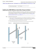
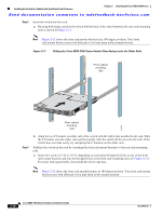
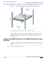
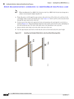
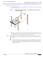
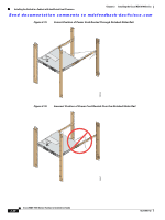
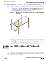
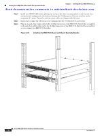
Chapter 2 Installing the Cisco MDS 9100 Series Installing the Switch in a Cabinet with Insufficient Front Clearance Send documentation comments to [email protected] Step 2 Insert the switch into the rack: a. Using both hands, position the switch with the back of the switch between the rear rack-mounting rails as shown in Figure 2-14. Figure 2-14 Sliding the Cisco MDS 9134 Switch or the Cisco MDS 9124 Switch (Rear-Facing) on the Notched Slider Rails Rear cabinet mounting rails Front cabinet mounting rails 182463 Step 3 b. Align the two C brackets on either side of the switch with the slider rails installed in the rack. Slide the C brackets onto the slider rails and then gently slide the switch all the way into the rack. If the switch does not slide easily, try realigning the C brackets on the slider rails. Connect the power cord that you previously routed through the open cutout of the slider rail to the switch, as shown in Figure 2-15. Limit the length of the power cord between the back of the chassis and the rail opening. Note If you failed to route the power cord through the open cutout of the slider rail as directed in Step 1, remove the switch and rails and remount the rails using the correct method. Do not connect the power cord by routing it over the top of the slider rail, as shown in Figure 2-16. This type of installation is hazardous. OL-17951-02 Cisco MDS 9100 Series Hardware Installation Guide 2-19
-
 1
1 -
2
-
3
-
4
-
5
-
6
-
7
-
8
-
9
-
10
-
11
-
12
-
13
-
14
-
15
-
16
-
17
-
18
-
19
-
20
-
21
-
22
-
23
-
24
-
25
-
26
-
27
-
28
-
29
-
30
-
31
-
32
-
33
-
34
-
35
-
36
-
37
-
38
-
39
-
40
-
41
-
 42
42 -
 43
43 -
 44
44 -
 45
45 -
 46
46 -
 47
47 -
 48
48 -
 49
49 -
 50
50 -
 51
51 -
 52
52 -
53
-
54
-
55
-
56
-
57
-
58
-
59
-
60
-
61
-
62
-
63
-
64
-
65
-
66
-
67
-
68
-
69
-
70
-
71
-
72
-
73
-
74
-
75
-
76
-
77
-
78
-
79
-
80
-
81
-
82
-
83
-
84
-
85
-
86
-
87
-
88
-
89
-
90
-
91
-
92
-
93
-
94
-
95
-
96
-
97
-
98
-
99
-
100
-
101
-
102
-
103
-
104
-
105
-
106
-
107
-
108
 |
 |
