HP Cisco MDS 9216A Cisco MDS 9200 Series Hardware Installation Guide (OL-16188 - Page 28
Interface Modules
 |
View all HP Cisco MDS 9216A manuals
Add to My Manuals
Save this manual to your list of manuals |
Page 28 highlights
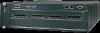
Interface Modules Chapter 1 Product Overview Interface Modules The nonremovable interface module is located above slot 1 (see Figure 1-7) and is identical for all Cisco MDS 9200 Series switches. It provides the following local and remote management interfaces: • RS-232 (EIA/TIA-232) console port with an RJ-45 connection that you can use to: - Configure the switch from the CLI. - Monitor network statistics and errors. - Configure SNMP agent parameters. • MGMT 10/100 Ethernet port with an RJ-45 connection that provides network management capabilities. • RS-232 COM1 port with a DB-9 connector that can be attached to a modem. Figure 1-7 Nonremoveable Interface Module of the Cisco MDS 9200 Series 1 3 5 6 78 MDS 9216i CONSOLE MGMT 10/100 COM1 9 2 4 STATUS SYSTEM RESET 116890 1 ESD socket (for ESD strap) 2 Grounding pad (beneath tape) 3 Status and System LEDs 4 Reset button 5 Console port 6 MGMT 10/100 Ethernet port (with integrated Link and Activity LEDs) 7 COM1 port 8 Asset tag 9 Interface module The clock module is also part of the interface module. Note The system clocks in the Cisco MDS 9200 Series have a field-measured mean time between failures (MTBF) of approximately 3.2 million hours or 365 years. In the event of a clock module failure, the system generates an error message and a switchover from one clock module to the other occurs, causing the system to reset automatically. 1-10 Cisco MDS 9200 Series Hardware Installation Guide OL-16188-01
-
 1
1 -
2
-
3
-
4
-
5
-
6
-
7
-
8
-
9
-
10
-
11
-
12
-
13
-
14
-
15
-
16
-
17
-
18
-
19
-
20
-
21
-
22
-
 23
23 -
 24
24 -
 25
25 -
 26
26 -
 27
27 -
 28
28 -
 29
29 -
 30
30 -
 31
31 -
 32
32 -
 33
33 -
34
-
35
-
36
-
37
-
38
-
39
-
40
-
41
-
42
-
43
-
44
-
45
-
46
-
47
-
48
-
49
-
50
-
51
-
52
-
53
-
54
-
55
-
56
-
57
-
58
-
59
-
60
-
61
-
62
-
63
-
64
-
65
-
66
-
67
-
68
-
69
-
70
-
71
-
72
-
73
-
74
-
75
-
76
-
77
-
78
-
79
-
80
-
81
-
82
-
83
-
84
-
85
-
86
-
87
-
88
-
89
-
90
-
91
-
92
-
93
-
94
-
95
-
96
-
97
-
98
-
99
-
100
-
101
-
102
-
103
-
104
-
105
-
106
-
107
-
108
-
109
-
110
-
111
-
112
-
113
-
114
-
115
-
116
-
117
-
118
-
119
-
120
-
121
-
122
-
123
-
124
-
125
-
126
-
127
-
128
-
129
-
130
-
131
-
132
-
133
-
134
-
135
-
136
-
137
-
138
-
139
-
140
-
141
-
142
-
143
-
144
-
145
-
146
-
147
-
148
-
149
-
150
-
151
-
152
-
153
-
154
-
155
-
156
-
157
-
158
-
159
-
160
-
161
-
162
-
163
-
164
 |
 |
