HP Cisco MDS 9216A Cisco MDS 9200 Series Hardware Installation Guide (OL-16188 - Page 97
Connecting the Cisco MDS 9200 Series
 |
View all HP Cisco MDS 9216A manuals
Add to My Manuals
Save this manual to your list of manuals |
Page 97 highlights
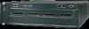
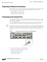
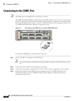
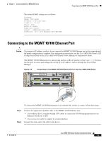
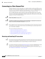
Send documentation comments to [email protected] 3 C H A P T E R Connecting the Cisco MDS 9200 Series The Cisco MDS 9200 Series provides the following types of ports: • Console port (interface module)-An RS-232 port that you can use to create a local management connection. • COM1 port (interface module)-An RS-232 port that you can use to connect to an external serial communication device such as a modem. • MGMT 10/100 Ethernet port (interface module)-An Ethernet port that you can use to access and manage the switch by IP address, such as through the CLI or Cisco Fabric Manager. • Fibre Channel ports (supervisor and switching modules)-Fibre Channel ports that you can use to connect to the SAN, or for in-band management. • Other port types provided by the optional module, if installed, such as the iSCSI and/or FCIP over Gigabit Ethernet ports on the 4-port or 8-port IPS modules. Caution When running power and data cables in overhead or subfloor cable trays, Cisco strongly recommends that power cables and other potential noise sources must be located as far away as practical from network cabling that terminates on Cisco equipment. In situations where long parallel cable runs cannot be separated by at least 3.3 ft (1 m), Cisco recommends shielding any potential noise sources by housing them in a grounded metallic conduit. This chapter includes the following topics: • Preparing for Network Connections, page 3-2 • Connecting to the Console Port, page 3-2 • Connecting to the COM1 Port, page 3-4 • Connecting to the MGMT 10/100 Ethernet Port, page 3-5 • Connecting to a Fibre Channel Port, page 3-6 OL-16188-01 Cisco MDS 9200 Series Hardware Installation Guide 3-1
-
 1
1 -
2
-
3
-
4
-
5
-
6
-
7
-
8
-
9
-
10
-
11
-
12
-
13
-
14
-
15
-
16
-
17
-
18
-
19
-
20
-
21
-
22
-
23
-
24
-
25
-
26
-
27
-
28
-
29
-
30
-
31
-
32
-
33
-
34
-
35
-
36
-
37
-
38
-
39
-
40
-
41
-
42
-
43
-
44
-
45
-
46
-
47
-
48
-
49
-
50
-
51
-
52
-
53
-
54
-
55
-
56
-
57
-
58
-
59
-
60
-
61
-
62
-
63
-
64
-
65
-
66
-
67
-
68
-
69
-
70
-
71
-
72
-
73
-
74
-
75
-
76
-
77
-
78
-
79
-
80
-
81
-
82
-
83
-
84
-
85
-
86
-
87
-
88
-
89
-
90
-
91
-
 92
92 -
 93
93 -
 94
94 -
 95
95 -
 96
96 -
 97
97 -
 98
98 -
 99
99 -
 100
100 -
 101
101 -
 102
102 -
103
-
104
-
105
-
106
-
107
-
108
-
109
-
110
-
111
-
112
-
113
-
114
-
115
-
116
-
117
-
118
-
119
-
120
-
121
-
122
-
123
-
124
-
125
-
126
-
127
-
128
-
129
-
130
-
131
-
132
-
133
-
134
-
135
-
136
-
137
-
138
-
139
-
140
-
141
-
142
-
143
-
144
-
145
-
146
-
147
-
148
-
149
-
150
-
151
-
152
-
153
-
154
-
155
-
156
-
157
-
158
-
159
-
160
-
161
-
162
-
163
-
164
 |
 |
