HP Cisco MDS 9216i Cisco MDS 9100 Series Hardware Installation Guide (OL-17951 - Page 51
Grounding the Switch
 |
View all HP Cisco MDS 9216i manuals
Add to My Manuals
Save this manual to your list of manuals |
Page 51 highlights
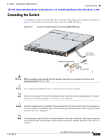
Chapter 2 Installing the Cisco MDS 9100 Series Grounding the Switch Send documentation comments to [email protected] Grounding the Switch A grounding pad with two threaded M4 holes is provided on the chassis for attaching a grounding lug. Figure 2-19 shows the system ground location on the Cisco MDS 9100 Series. Figure 2-19 Location of Switch Ground on the Cisco MDS 9100 Series Grounding pad location System grounding pad Grounding lug Wire Screws (M4) 94943 Warning When installing or replacing the unit, the ground connection must always be made first and disconnected last. Statement 1046 Caution We recommend grounding the chassis, even if the rack is already grounded. Note If the rack is less than 25-in. (635 mm) deep, the slider rails will cover the grounding hole. Therefore, the rack must either be grounded or at least 25-in. (635 mm) deep. Caution All power supplies must be grounded. The receptacles of the AC power cables used to provide power to the chassis must be the grounding type, and the grounding conductors should connect to protective earth ground at the service equipment. Note The grounding lug must be NRTL listed and compatible with copper conductors. Only copper conductors (wires) must be used and the copper conductor must comply with National Electrical Code (NEC) for ampacity. OL-17951-02 Cisco MDS 9100 Series Hardware Installation Guide 2-23
-
 1
1 -
2
-
3
-
4
-
5
-
6
-
7
-
8
-
9
-
10
-
11
-
12
-
13
-
14
-
15
-
16
-
17
-
18
-
19
-
20
-
21
-
22
-
23
-
24
-
25
-
26
-
27
-
28
-
29
-
30
-
31
-
32
-
33
-
34
-
35
-
36
-
37
-
38
-
39
-
40
-
41
-
42
-
43
-
44
-
45
-
 46
46 -
 47
47 -
 48
48 -
 49
49 -
 50
50 -
 51
51 -
 52
52 -
 53
53 -
 54
54 -
 55
55 -
 56
56 -
57
-
58
-
59
-
60
-
61
-
62
-
63
-
64
-
65
-
66
-
67
-
68
-
69
-
70
-
71
-
72
-
73
-
74
-
75
-
76
-
77
-
78
-
79
-
80
-
81
-
82
-
83
-
84
-
85
-
86
-
87
-
88
-
89
-
90
-
91
-
92
-
93
-
94
-
95
-
96
-
97
-
98
-
99
-
100
-
101
-
102
-
103
-
104
-
105
-
106
-
107
-
108
 |
 |
