HP Dc7700 Hardware Reference Guide - dc7700 CMT - Page 38
Connecting the Drive Cables Optical Drive shown,
 |
UPC - 882780715318
View all HP Dc7700 manuals
Add to My Manuals
Save this manual to your list of manuals |
Page 38 highlights
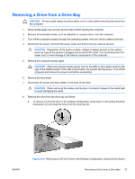
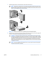
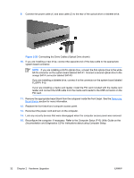
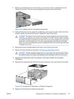
9. Connect the power cable (1) and data cable (2) to the rear of the optical drive or diskette drive. Figure 2-20 Connecting the Drive Cables (Optical Drive shown) 10. If you are installing a new drive, connect the opposite end of the data cable to the appropriate system board connector. NOTE If you are installing a SATA optical drive, connect the first optical drive to the white SATA connector on the system board labeled SATA1. Connect a second optical drive to the orange SATA connector labeled SATA3. If you are installing a diskette drive, connect it to the connector on the system board labeled FLOPPY P10. If your are installing a media card reader, install the PCI card included with the media card reader and connect the USB cable from the media card reader to the USB connector on the PCI card. 11. Remove the appropriate bezel blank from the subpanel inside the front bezel. See the Removing Bezel Blanks section for more information. 12. Replace the front bezel and computer access panel. 13. Reconnect the power cord and turn on the computer. 14. Lock any security devices that were disengaged when the computer access panel was removed. 15. Reconfigure the computer, if necessary. Refer to the Computer Setup (F10) Utility Guide on the Documentation and Diagnostics CD for instructions about using Computer Setup. 32 Chapter 2 Hardware Upgrades ENWW
-
 1
1 -
2
-
3
-
4
-
5
-
6
-
7
-
8
-
9
-
10
-
11
-
12
-
13
-
14
-
15
-
16
-
17
-
18
-
19
-
20
-
21
-
22
-
23
-
24
-
25
-
26
-
27
-
28
-
29
-
30
-
31
-
32
-
 33
33 -
 34
34 -
 35
35 -
 36
36 -
 37
37 -
 38
38 -
 39
39 -
 40
40 -
 41
41 -
 42
42 -
 43
43 -
44
-
45
-
46
-
47
-
48
-
49
-
50
-
51
-
52
-
53
-
54
-
55
-
56
-
57
-
58
-
59
-
60
 |
 |
