HP Dv6 1360us HP Pavilion dv6 Entertainment PC - Maintenance and Service Guide - Page 77
of the system board until it rests at approximately a 45-degree angle., Lift up on the right side
 |
UPC - 884962549117
View all HP Dv6 1360us manuals
Add to My Manuals
Save this manual to your list of manuals |
Page 77 highlights
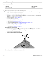
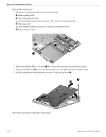
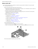
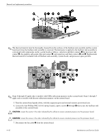
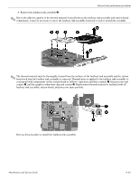
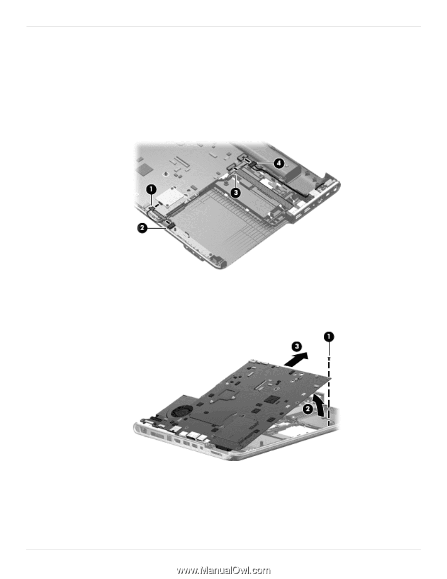
Removal and replacement procedures Remove the system board: 1. Disconnect the following cables from the system board: 1 Modem module cable 2 Audio/infrared board cable ✎ The audio/infrared board cable connects to a LIF connector on the system board. 3 USB board cable ✎ The USB board cable connects to a LIF connector on the system board. 4 Power connector cable 2. Remove the Phillips PM2.5×7.0 screw 1 that secures the system board to the base enclosure. 3. Lift up on the right side 2 of the system board until it rests at approximately a 45-degree angle. 4. Lift the system board to the right and up and out of the base enclosure 3. Reverse this procedure to install the system board. 4-38 Maintenance and Service Guide
-
 1
1 -
2
-
3
-
4
-
5
-
6
-
7
-
8
-
9
-
10
-
11
-
12
-
13
-
14
-
15
-
16
-
17
-
18
-
19
-
20
-
21
-
22
-
23
-
24
-
25
-
26
-
27
-
28
-
29
-
30
-
31
-
32
-
33
-
34
-
35
-
36
-
37
-
38
-
39
-
40
-
41
-
42
-
43
-
44
-
45
-
46
-
47
-
48
-
49
-
50
-
51
-
52
-
53
-
54
-
55
-
56
-
57
-
58
-
59
-
60
-
61
-
62
-
63
-
64
-
65
-
66
-
67
-
68
-
69
-
70
-
71
-
 72
72 -
 73
73 -
 74
74 -
 75
75 -
 76
76 -
 77
77 -
 78
78 -
 79
79 -
 80
80 -
 81
81 -
 82
82 -
83
-
84
-
85
-
86
-
87
-
88
-
89
-
90
-
91
-
92
-
93
-
94
-
95
-
96
-
97
-
98
-
99
-
100
-
101
-
102
-
103
-
104
-
105
-
106
-
107
-
108
-
109
-
110
-
111
-
112
-
113
-
114
-
115
-
116
-
117
-
118
-
119
-
120
-
121
-
122
-
123
-
124
-
125
-
126
-
127
-
128
-
129
 |
 |
4–38
Maintenance and Service Guide
Removal and replacement procedures
Remove the system board:
1. Disconnect the following cables from the system board:
1
Modem module cable
2
Audio/infrared board cable
✎
The audio/infrared board cable connects to a LIF connector on the system board.
3
USB board cable
✎
The USB board cable connects to a LIF connector on the system board.
4
Power connector cable
2. Remove the Phillips PM2.5×7.0 screw
1
that secures the system board to the base enclosure.
3. Lift up on the right side
2
of the system board until it rests at approximately a 45-degree angle.
4. Lift the system board to the right and up and out of the base enclosure
3
.
Reverse this procedure to install the system board.