HP Dv6 1360us HP Pavilion dv6 Entertainment PC - Maintenance and Service Guide - Page 81
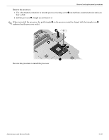
Loosen the four Phillips PM2.5×14.0 spring-loaded, captive screws, Turn the system board upside down
 |
UPC - 884962549117
View all HP Dv6 1360us manuals
Add to My Manuals
Save this manual to your list of manuals |
Page 81 highlights
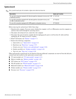
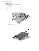
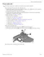
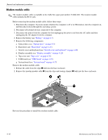
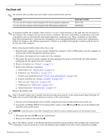
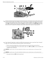
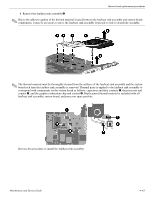
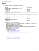
Removal and replacement procedures ✎ The thermal material must be thoroughly cleaned from the surfaces of the fan/heat sink assembly and the system board each time the fan/heat sink assembly is removed. Thermal paste is applied to the fan/heat sink assembly to correspond with components on the system board as follows: capacitors and their contacts 1 the processor and contact 2, the graphics subsystem chip and contact 3, and capacitors and their contacts 4 and 5. Replacement thermal material is included with all fan/heat sink assembly, system board, and processor spare part kits. ✎ Steps 6 through 10 apply only to models with UMA subsystem memory on the system board. Steps 1 through 5 apply only to models with discrete subsystem memory on the system board. 5. Turn the system board upside down, with the expansion port and external monitor port toward you. 6. Loosen the four Phillips PM2.5×14.0 spring-loaded, captive screws 1 through 4 that secure the fan/heat sink assembly to the system board. Ä CAUTION: Loosen the screws in the order indicated by the callouts to ensure consistent pressure over the processor board. Ä CAUTION: Loosen the screws in the order indicated by the callouts to ensure consistent pressure over the processor board. 7. Disconnect the fan cable 5 from the system board. 4-42 Maintenance and Service Guide
-
 1
1 -
2
-
3
-
4
-
5
-
6
-
7
-
8
-
9
-
10
-
11
-
12
-
13
-
14
-
15
-
16
-
17
-
18
-
19
-
20
-
21
-
22
-
23
-
24
-
25
-
26
-
27
-
28
-
29
-
30
-
31
-
32
-
33
-
34
-
35
-
36
-
37
-
38
-
39
-
40
-
41
-
42
-
43
-
44
-
45
-
46
-
47
-
48
-
49
-
50
-
51
-
52
-
53
-
54
-
55
-
56
-
57
-
58
-
59
-
60
-
61
-
62
-
63
-
64
-
65
-
66
-
67
-
68
-
69
-
70
-
71
-
72
-
73
-
74
-
75
-
 76
76 -
 77
77 -
 78
78 -
 79
79 -
 80
80 -
 81
81 -
 82
82 -
 83
83 -
 84
84 -
 85
85 -
 86
86 -
87
-
88
-
89
-
90
-
91
-
92
-
93
-
94
-
95
-
96
-
97
-
98
-
99
-
100
-
101
-
102
-
103
-
104
-
105
-
106
-
107
-
108
-
109
-
110
-
111
-
112
-
113
-
114
-
115
-
116
-
117
-
118
-
119
-
120
-
121
-
122
-
123
-
124
-
125
-
126
-
127
-
128
-
129
 |
 |
