HP Envy 13-1003xx HP ENVY 13 - Maintenance and Service Guide - Page 48
Display assembly, built into the system board.
 |
View all HP Envy 13-1003xx manuals
Add to My Manuals
Save this manual to your list of manuals |
Page 48 highlights
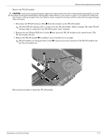
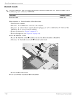
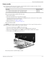
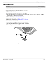
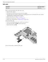
Removal and replacement procedures Display assembly ✎ The display assembly spare part kit includes a webcam module and cable, microphone and cable, 2 WLAN antenna transceivers and cables, nameplate, and logo. Description 13.1-in, AntiGlare, LED high-definition+ (1600 × 900) display assembly 13.1-in, AntiGlare, LED high-definition (1366 × 768) display assembly Spare part number 538320-001 538319-001 Before removing the display assembly, follow these steps: 1. Shut down the computer. 2. Disconnect all external devices connected to the computer. 3. Disconnect the power from the computer by first unplugging the power cord from the AC outlet, and then unplugging the AC adapter from the computer. 4. Remove the battery (see "Battery" on page 4-7). 5. Remove the top cover (see "Top cover" on page 4-8). Remove the display assembly: Ä CAUTION: Support the display assembly when removing the following screws. Failure to support the display assembly can result in damage to the display assembly and other computer components. 1. Disconnect the display panel cable 1 from the system board. 2. Remove the wireless antenna cables from the rubber clips 2 built into the system board. 3. Remove the two Phillips PM2.0×5.0 screws 3 that secure the display assembly to the computer. 4. Lift the display assembly 4 straight up and remove it. Reverse this procedure to install the display assembly. Maintenance and Service Guide 4-19
-
 1
1 -
2
-
3
-
4
-
5
-
6
-
7
-
8
-
9
-
10
-
11
-
12
-
13
-
14
-
15
-
16
-
17
-
18
-
19
-
20
-
21
-
22
-
23
-
24
-
25
-
26
-
27
-
28
-
29
-
30
-
31
-
32
-
33
-
34
-
35
-
36
-
37
-
38
-
39
-
40
-
41
-
42
-
 43
43 -
 44
44 -
 45
45 -
 46
46 -
 47
47 -
 48
48 -
 49
49 -
 50
50 -
 51
51 -
 52
52 -
 53
53 -
54
-
55
-
56
-
57
-
58
-
59
-
60
-
61
-
62
-
63
-
64
-
65
-
66
-
67
-
68
-
69
-
70
-
71
-
72
-
73
-
74
-
75
-
76
-
77
-
78
-
79
-
80
-
81
-
82
-
83
-
84
-
85
-
86
-
87
-
88
-
89
-
90
-
91
-
92
-
93
-
94
-
95
-
96
-
97
-
98
-
99
-
100
-
101
-
102
-
103
-
104
-
105
 |
 |
