HP J4903A User Manual
HP J4903A Manual
 |
View all HP J4903A manuals
Add to My Manuals
Save this manual to your list of manuals |
HP J4903A manual content summary:
- HP J4903A | User Manual - Page 1
hp procurve switch 2800 series installation and getting started guide www.hp.com/go/hpprocurve - HP J4903A | User Manual - Page 2
- HP J4903A | User Manual - Page 3
HP ProCurve Switch 2800 Series Installation and Getting Started Guide - HP J4903A | User Manual - Page 4
software on equipment that is not furnished by Hewlett-Packard. Warranty See the Customer Support/Warranty booklet included with the product. A copy of the specific warranty terms applicable to your HewlettPackard products and replacement parts can be obtained from your HP Sales and Service Office - HP J4903A | User Manual - Page 5
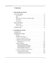
Passes Self Test 2-9 LED Behavior 2-10 4. Mount the Switch 2-11 Rack or Cabinet Mounting 2-11 Rack Mounting the Switch 2848 2-12 Rack Mounting the Switch 2824 2-14 Horizontal Surface Mounting 2-17 5. Connect the Switch to a Power Source 2-17 6. Connect the Network Cables 2-18 Using the - HP J4903A | User Manual - Page 6
4-9 Checking Console Messages 4-9 Testing Twisted-Pair Cabling 4-10 Testing Switch-to-Device Network Communications 4-10 Testing End-to-End Network Communications 4-10 Restoring the Factory Default Configuration 4-11 Downloading New Switch Software 4-12 HP Customer Support Services 4-12 2 - HP J4903A | User Manual - Page 7
Before Calling Support 4-12 A Switch Specifications Physical A-1 Electrical A-1 Environmental A-1 Acoustic A-2 Connectors A-2 Safety A-2 Lasers A-2 B Switch Ports and Network Cables Switch Ports B-1 Twisted-Pair Cables B-1 Mode Conditioning Patch Cord for Gigabit-LX B-3 Installing the - HP J4903A | User Manual - Page 8
Consideraciones sobre seguridad C-5 Safety Information (Japan C-6 Safety Information (China C-7 EMC Regulatory Statements C-8 U.S.A C-8 Canada C-8 Australia/New Zealand C-8 Japan C-8 Korea C-9 Taiwan C-9 European Community C-10 4 - HP J4903A | User Manual - Page 9
that can be used to build high-performance switched workgroup networks. These switches are store-and-forward devices offering low latency for highspeed networking. HP ProCurve Switch 2824 (HPJ4903A) Power Fault hp procurve switch 2824 J4903A 12345678 9 10 11 12 13 14 15 16 17 18 19 20 1 79 - HP J4903A | User Manual - Page 10
devices, and can build a switched network infrastructure by connecting the switch to hubs, other switches, or routers. In addition, the Switch 2800 Series devices offer full network management capabilities. This chapter describes the HP ProCurve Switch 2824 and Switch 2848, including: ■ front and - HP J4903A | User Manual - Page 11
Fan and RPS Status LEDs Switch port LEDs HP ProCurve Switch 2824 Power Fault hp procurve switch 2824 J4903A 12345678 9 10 11 12 T 48 M 44 Dual-Personality Ports: 10/100/1000-T (T) or Mini-GBIC (M) Reset and Clear buttons LED Mode select button and indicator LEDs 10/100/1000Base-T RJ-45 - HP J4903A | User Manual - Page 12
a supported HP ProCurve mini-GBIC for fiber-optic connections. The RJ-45 connectors support the IEEE Auto MDI/MDI-X feature, which means you can use either straight-through or crossover twisted-pair cables to connect any network device to the switch. Dual-Personality Port Operation. By default, the - HP J4903A | User Manual - Page 13
power. On On briefly after the switch is powered on or reset, at the beginning of switch self test. If this LED is on for a prolonged time, the switch has encountered a fatal hardware failure, or has failed its self test. See chapter 4, "Troubleshooting" for more information. Test Off The - HP J4903A | User Manual - Page 14
the mini-GBIC connector is enabled. Normal operation, all fans are ok. One of the unit's fans has failed. The switch Fault LED will be blinking simultaneously. Normal operation. An HP ProCurve EPS/RPS unit is connected and operating correctly. The EPS/RPS could be powering the unit - see table below - HP J4903A | User Manual - Page 15
to the next. Port LED (one for each port) Power Fault hp procurve switch 2824 12345678 9 10 11 12 13 14 15 16 17 18 19 20 1 79 19 Dual-Person J4903A Console Status LED Lnk 21 RPS Mode Act Fan FDx T Test Spd M Reset Clear Spd mode: off = 10 Mbps, flash = 100 Mbps, on = 1000 - HP J4903A | User Manual - Page 16
browser interface, and SNMP management are removed, and the factory default configuration is restored to the switch. For the specific method to restore the factory default configuration, see "Restoring the Factory Default Configuration" on page 11 in chapter 4, "Troubleshooting" of this manual. 1-8 - HP J4903A | User Manual - Page 17
of the Switch Back of the Switch HP ProCurve Switch 2824 (HPJ4903A) HP ProCurve RPS Input Line: 50/60 Hz. 100-127 V~ 0.6A (0,6A) 200-240 V~ 0.3A (0,3A) Cooling vents - make sure this is not obstructed for proper switch operation RPS Input AC power connector HP ProCurve Switch 2848 (HPJ4904A - HP J4903A | User Manual - Page 18
attached end nodes into logical groupings that fit your business needs. ■ support for many advanced features to enhance network performance- for a description, see the Management and Configuration Guide, which is on the Documentation CD-ROM included with the switch. ■ download of new switch software - HP J4903A | User Manual - Page 19
devices, including the Management and Configuration Guide, and for most other HP ProCurve switches) ■ HP ProCurve Manager - CD ROM and booklet ■ Console cable ■ Customer Support/Warranty booklet ■ Accessory kits (5064-5085) for Switch 2824 (5069-5705) for Switch 2848 two mounting brackets two - HP J4903A | User Manual - Page 20
Switch Included Parts ■ Power cord, one of the following: Australia/New Zealand China Continental Europe Denmark Japan Switzerland United Kingdom/Hong Kong/Singapore United States/Canada/Mexico 8120-6803 8120-8377 8120-6802 8120-6806 8120-6804 8120-6807 8120-8709 8120-6805 Installing the Switch - HP J4903A | User Manual - Page 21
with the RPS, to the back of the switch. 8. Connect a console to the switch (optional-page 2-22). You may wish to modify the switch's configuration, for example, to configure an IP address so it can be managed using a web browser, from an SNMP network management station, or through a Telnet session - HP J4903A | User Manual - Page 22
. To determine the possibility of overloading the supply circuits, add together the ampere ratings of all devices installed on the same circuit as the switch and compare the total with the rating limit for the circuit. The maximum ampere ratings are usually printed on the devices near the AC power - HP J4903A | User Manual - Page 23
specifications. See the following table for cable types and lengths, and see appendix B, "Cables and Connectors" for more information: Table 2-1. Summary of Cable Types to Use With the Switch to any network devices including end nodes, such as computers, or to other switches, hubs, and routers. Note - HP J4903A | User Manual - Page 24
its location and orientation relative to other devices and equipment: • In the front of the switch, leave at least 7.6 cm (3 inches) of space for the twisted-pair and fiber-optic cabling. • In the back of the switch, leave at least 3.8 cm (1 1/2 inches) of space for the power cord. • On the sides of - HP J4903A | User Manual - Page 25
having to power off the switch. Use only HP ProCurve mini-GBICs. ■ The mini manual was printed, the supported mini-GBICs include the following: ■ HP ProCurve Gigabit-SX-LC mini-GBIC (J4858A) ■ HP ProCurve Gigabit-LX-LC mini-GBIC (J4859A) ■ HP ProCurve Gigabit-LH-LC mini-GBIC (J4860A) The HP ProCurve - HP J4903A | User Manual - Page 26
Procedures Removing the mini-GBICs: Note You should disconnect the network cable from the mini-GBIC before removing it from the switch. Depending on when you purchased your HP ProCurve mini-GBIC, it may have either of three different release mechanisms: a plastic tab on the bottom of the mini-GBIC - HP J4903A | User Manual - Page 27
and either 50 or 60 Hz. No voltage range settings are required. If your installation requires a different power cord than the one supplied with the switch, be sure to use a power cord displaying the mark of the safety agency that defines the regulations for power cords in your country. The mark - HP J4903A | User Manual - Page 28
Procedures 2. Check the LEDs on the switch as described below. Switch 2824 Switch port LEDs Power Fault hp procurve switch 2824 J4903A Console 12345678 9 10 11 12 13 14 15 16 1 1 79 Reset Clear Status LED Lnk RPS Mode Act Fan FDx Test Spd Spd mode: off = 10 Mbps, flash - HP J4903A | User Manual - Page 29
network devices, the LEDs behave according to the LED Mode selected. In the default view mode (Link), the LEDs should be on. - If the ports Troubleshooting" for diagnostic help. 4. Mount the Switch After the switch passes self test, you are ready to mount the switch in a stable location. The Switch - HP J4903A | User Manual - Page 30
M4 screws Note The mounting brackets have multiple mounting holes and can be rotated allowing for a wide variety of mounting options. These include mounting the switch so its front face is flush with the face of the rack, or mounting it in a more balanced position as shown in the illustration - HP J4903A | User Manual - Page 31
Installing the Switch Installing the Switch Installation Procedures 2. Hold the switch with attached brackets up to the rack and move it vertically until rack holes line up with the bracket holes, then insert and tighten the four number 12-24 screws holding the brackets to the rack. 2-13 - HP J4903A | User Manual - Page 32
Installation Procedures Rack Mounting the Switch 2824 1. Use a #1 Phillips (cross-head) screwdriver and attach the mounting brackets to the switch with the included 8-mm M4 screws. Installing the Switch 8 mm M4 screws Note The mounting brackets have multiple mounting holes and can be rotated - HP J4903A | User Manual - Page 33
the same level in each upright. Partially install a screw into the top hole of a close (0.5-inch) pair on both sides of the rack 3. Place the switch in the rack and lower it so the notches in the bottom of the bracket slide onto the screws, then tighten these screws. Lower - HP J4903A | User Manual - Page 34
Installing the Switch Installing the Switch Installation Procedures 4. Install the other number 12-24 screw into the upper hole in each bracket. Tighten these screws. 2-16 - HP J4903A | User Manual - Page 35
Installation Procedures Horizontal Surface Mounting Place the switch on a table or other horizontal surface. The switch comes with rubber feet in the accessory kit that can be used to help keep the switch from sliding on the surface. Attach the rubber feet to the four corners on the bottom of the - HP J4903A | User Manual - Page 36
end node) is at the other end of the cable. RJ-45 connector If the Link LED does not go on when the network cable is connected to the port, see "Diagnosing with the LEDs" on page 4-4, in chapter 4, "Troubleshooting have any mini-GBICs installed in the switch, the type of network connections you - HP J4903A | User Manual - Page 37
referred to as the EPS/RPS)" (J8168A) is an accessory product for the Switch 2800 Series devices and specific other HP ProCurve switches. The EPS/RPS provides redundant power to any one of up to six switch products, to back up the power supply in the switch in case of loss of AC power, or a fault - HP J4903A | User Manual - Page 38
Device Connected Power Status Message Off Off Off Nothing Connected On or Off Off On Not a valid state - should never happen Off On Off Switch is connected, RPS is available but not required Off On On RPS is powering the connected device Blinking Off Blinking RPS port is in - HP J4903A | User Manual - Page 39
between an EPS/RPS device and a Switch device. Console Switch 2848, RPS input port HP ProCurve RPS Input Line: 50/60 Hz. switch within 1ms. The EPS/RPS supports hot plugging of the EPS/RPS cable without causing a reboot of the switch or causing the power supply in either the EPS/RPS or switch - HP J4903A | User Manual - Page 40
activity statistics ■ Modify the switch's configuration to optimize switch performance, enhance network traffic control, and improve network security ■ Read the event log and access diagnostic tools to help in troubleshooting ■ Download new software to the switch ■ Add passwords to control access to - HP J4903A | User Manual - Page 41
CLI) prompt, for example: HP ProCurve Switch 2848# If you want to continue with console management of the switch at this time, see chapter 3, "Configuring the Switch" for some basic configuration steps. For more detailed information, refer to the Management and Configuration Guide, which is on the - HP J4903A | User Manual - Page 42
/go/hpprocurve. As a Desktop Switch Server with Gigabit Ethernet NIC HP ProCurve Switch 2824 Power Fault PCs, local servers, and peripherals LEGEND: Fast Ethernet cable Gigabit Ethernet cable The Switch is designed to be used primarily as a desktop switch to which end nodes, printers and other - HP J4903A | User Manual - Page 43
Network Topologies Servers with Gigabit Ethernet NIC Power Fault Fast Ethernet Switch Power Fault hp procurve switch 2650 J4899A Act FDx Max HP ProCurve Switch 2824 To backbone Fast Ethernet Switch Power Fault hp procurve switch 2650 J4899A Act FDx Max PCs, local servers, and peripherals - HP J4903A | User Manual - Page 44
between the switch and the hubs, and between the switch and end nodes or servers can be through category 5 "straight-through" or "crossover" twistedpair cable. Category 3 or 4 cable can also be used if the connection is 10 Mbps only. In all cases, the device ports must be configured to auto - HP J4903A | User Manual - Page 45
4 4 B xl module D xl module Power Fault HP ProCurve Switch 2824 HP ProCurve Switch 5304xl Gigabit link (use fiber if over 100 meters) Server HP ProCurve Switch 2848 Power Fault hp procurve switch 5304xl J4850A Console Link 1 1 J4878A Mode Power Status Fault 1 2 A B C D E F G H Reset - HP J4903A | User Manual - Page 46
information on stacking Switches, please see the Management and Configuration Guide, which is on the Documentation CD-ROM that came with the switch. HP ProCurve Switch 2848 Power Fault HP ProCurve Switch 2848 Power Fault HP ProCurve Switch 2824 Power Fault HP ProCurve Switch 2824 Power Fault To - HP J4903A | User Manual - Page 47
ProCurve Switch 2824 Power Fault HP ProCurve Switch 2824 Power Fault HP ProCurve Switch 2848 Power Fault HP ProCurve Switch 2848 Power Fault HP ProCurve Switch 2848 Power Fault RPS STP XRRP Power Fault hp procurve switch 5308xl J4819A Console Link 1 1 J4878A Mode Status 1 2 ABCDEF GH Reset - HP J4903A | User Manual - Page 48
Installing the Switch Installing the Switch Sample Network Topologies 2-30 - HP J4903A | User Manual - Page 49
, please see the Management and Configuration Guide, which is on the Documentation CD-ROM that came with your switch. Recommended Minimal Configuration In the factory default configuration, the switch has no IP (Internet Protocol) address and subnet mask, and no passwords. In this state, it can - HP J4903A | User Manual - Page 50
the switch model number, for example: HP ProCurve Switch 2824# 2. At the prompt, enter the setup command to display the Switch Setup screen. The following illustration shows the Setup screen with the default settings. Configuring the Switch 3. Use the [Tab] key to select the Manager Password field - HP J4903A | User Manual - Page 51
you set IP Config to Manual, then enter an IP address compatible with your network. Note: The IP address and subnet mask assigned for the switch must be compatible with the IP addressing used in your network. For more information on IP addressing, see the Management and Configuration Guide, which - HP J4903A | User Manual - Page 52
see the Management and Configuration Guide, which is on the Documentation CD-ROM that came with your switch. To Recover from a Lost Manager Password: If you cannot start a console session at the manager level because of a lost Manager password, you can clear all passwords and user names by getting - HP J4903A | User Manual - Page 53
is on the same subnet as the switch and connect to the switch's IP address. 3. You will see the copyright page and the message "Press any key to continue". Press a key, and you will then see the switch console command (CLI) prompt, for example: HP ProCurve Switch 2824# Enter help or ? to see a list - HP J4903A | User Manual - Page 54
Configuring the Switch Using the IP Address for Remote Switch Management For more information on using the web browser interface, please see the Management and Configuration Guide, which is on the Documentation CD-ROM that came with your switch. An extensive help system is also available for the web - HP J4903A | User Manual - Page 55
■ hardware diagnostic tests (page 4-9) ■ restoring the factory default configuration (page 4-11) ■ downloading new software to the Switch 2800 Series devices (page 4-12) ■ HP Customer Support Services (page 4-12) Basic Troubleshooting Tips Most problems are caused by the following situations. Check - HP J4903A | User Manual - Page 56
topology. If you no longer experience the problems, the new topology is probably at fault. Sample topologies are shown at the end of chapter 2 in this book, and some topology configuration guidelines can be found on the HP ProCurve web site, http://www.hp.com/go/hpprocurve. In addition, you should - HP J4903A | User Manual - Page 57
and Configuration Guide, which is on the Documentation CD-ROM that came with your switch. For more information on possible network problems and their solutions, refer to the technical note "Troubleshooting LAN Performance and Intermittent Connectivity Problems", which can be found on the HP ProCurve - HP J4903A | User Manual - Page 58
Troubleshooting Diagnosing with the LEDs Diagnosing with the LEDs Table 3-1 shows LED patterns on the switch and the switch modules that indicate problem conditions. 1. Check in the table for the LED pattern you see on your switch. 2. Refer to the corresponding diagnostic tip on the next few pages - HP J4903A | User Manual - Page 59
does not exceed normal room temperature, but for best operation, the switch should be replaced. Contact your HP-authorized LAN dealer, or use the electronic support services from HP to get assistance. See the Customer Support/Warranty booklet for more information. ➎ The network port Try power - HP J4903A | User Manual - Page 60
all patch cables from any end devices, including the switch, to any patch panels in the cabling path. • Verify that the port has not been disabled through a switch configuration change. You can use the console interface, or, if you have configured an IP address on the switch, use the web browser - HP J4903A | User Manual - Page 61
see how the port is configured for these features. For software troubleshooting tips, see the chapter "Troubleshooting" in the Management and Configuration Guide, which is on the Documentation CD-ROM that came with your switch. Make sure also, that the device at the other end of the connection is - HP J4903A | User Manual - Page 62
is provided with your switch. The console interface is also accessible through a Telnet connection. For more information on using these software tools to diagnose and manage your switch, see the "Troubleshooting" chapter in the Management and Configuration Guide, which is on the Documentation - HP J4903A | User Manual - Page 63
Messages Useful diagnostic messages may be displayed on the console screen when the switch is reset. To connect a PC running a VT-100 terminal emulator program or a standard VT-100 terminal to the switch's Console Port and configure it to run at 9600 baud, and with the other terminal communication - HP J4903A | User Manual - Page 64
. For more information, see the Management and Configuration Guide, which is on the Documentation CD-ROM that came with your switch. Testing End-to-End Network Communications Both the switch and the cabling can be tested by running an end-to-end communications test -- a test that sends known data - HP J4903A | User Manual - Page 65
the Factory Default Configuration As part of your troubleshooting process on the Switch, it may become necessary to return the switch configuration to the factory default settings. This process momentarily interrupts the switch operation, clears any passwords, clears the console event log, resets - HP J4903A | User Manual - Page 66
Management and Configuration Guide, which is on the Documentation CDROM that came with your switch. The new switch software would be available on the HP ProCurve web site, http://www.hp.com/go/hpprocurve. HP Customer Support Services If you are still having trouble with your switch, Hewlett-Packard - HP J4903A | User Manual - Page 67
Switch Specifications A Switch Specifications Physical Width: Depth: Height: Weight: 2824 (J4903A) 44.3 cm (17.42 in) 36.7 cm (14.4 in) 4.4 cm (1.73 in) 4.62 kg (10.20 lbs) 2848 (J4904A) 44.3 cm (17.42 in) 43.0 cm (16.9 in) 4.4 cm (1.73 in) 4.88 kg (10.75 lbs) Electrical The switch - HP J4903A | User Manual - Page 68
Switch Specifications Switch Specifications Acoustic Geraeuschemission LwA=52 dB am fiktiven Arbeitsplatz nach DIN 45635 T. -LX LC mini-GBIC, both of which can be installed in the Switch 2800 Series devices, are Class 1 Laser Products. Laser Klasse 1 These mini-GBICs comply with IEC 825-2: 1993. A-2 - HP J4903A | User Manual - Page 69
for cables that should be used with the Switch 2800 Series devices, including minimum pin-out information and specifications for twisted-pair cables. Incorrectly wired cabling is the most common cause of problems for LAN communications. HP recommends that you work with a qualified LAN cable - HP J4903A | User Manual - Page 70
Crosstalk (ELFEXT) and Return Loss. When testing your cabling, be sure to include the patch cables that connect the switch and other end devices to the patch panels on your site. The patch cables are frequently overlooked when testing cable and they must also comply with the cabling - HP J4903A | User Manual - Page 71
patch cords between the Gigabit-LX port in your switch and your multimode fiberoptic network cabling, and between the Gigabit-LX transmission device and the network cabling at the other end of the multimode fiber-optic cable run. A patch cord must be installed at both ends. The patch cord consists of - HP J4903A | User Manual - Page 72
of recommended Mode Conditioning Patch Cords that have been tested and verified to operate correctly with the HP ProCurve Gigabit-LX Transceiver and HP ProCurve Gigabit-LX LC mini-GBIC. The list is on the HP ProCurve web site, http://www.hp.com/go/hpprocurve, in the Technical Support section. B-4 - HP J4903A | User Manual - Page 73
configurations though, for example 100 Mbps/full duplex, the port operates as MDI-X only and the correct cable type must be used: for connections to MDI ports, such as end nodes, use a "straight-through" cable; for connections to MDI-X ports, such as on hubs and other switches , as supported by the - HP J4903A | User Manual - Page 74
MDI/MDI-X operation of the 10/100 ports on the switch, for all network connections, to PCs, servers or other end nodes, or to hubs or other switches, you can use "straight-through" cables. If any of these ports are given a fixed configuration, for example 100 Mbps/ Full Duplex, the ports operate as - HP J4903A | User Manual - Page 75
also allows you to use "crossover" cables for all network connections, to PCs, servers or other end nodes, or to hubs or other switches. If any of these ports are given a fixed configuration, for example 100 Mbps/ Full Duplex, the ports operate as MDI-X ports, and crossover cables must be then - HP J4903A | User Manual - Page 76
-Through Twisted-Pair Cable for 1000 Mbps Network Connections 1000Base-T connections require that all four pairs of wires be connected. Cable Diagram Switch Ports and Network Cables Note . B-8 Pins 1 and 2 on connector "A" must be wired as a twisted pair to pins 1 and 2 on connector "B". Pins - HP J4903A | User Manual - Page 77
manual denotes a hazard that can cause injury or death. A CAUTION in the manual Servicing There are no user-serviceable parts inside these products. Any servicing, adjustment, maintenance, or repair must be performed only by service-trained personnel. These products do not have a power switch - HP J4903A | User Manual - Page 78
Safety and EMC Regulatory Statements Informations concernant la sécurité Informations concernant la sécurité ! WARNING CAUTION Symbole de référence à la documentation. Si le produit est marqué de ce symbole, reportez-vous à la documentation du produit afin d'obtenir des informations plus détaillé - HP J4903A | User Manual - Page 79
Safety and EMC Regulatory Statements Hinweise zur Sicherheit Hinweise zur Sicherheit ! WARNING CAUTION Symbol für Dokumentationsverweis. Wenn das Produkt mit diesem Symbol markiert ist, schlagen Sie bitte in der Produktdokumentation nach, um mehr Informationen über das Produkt zu erhalten. Eine - HP J4903A | User Manual - Page 80
Safety and EMC Regulatory Statements Considerazioni sulla sicurezza Considerazioni sulla sicurezza ! WARNING CAUTION Simbolo di riferimento alla documentazione. Se il prodotto è contrassegnato da questo simbolo, fare riferimento alla documentazione sul prodotto per ulteriori informazioni su di - HP J4903A | User Manual - Page 81
Safety and EMC Regulatory Statements Consideraciones sobre seguridad Consideraciones sobre seguridad ! WARNING CAUTION Símbolo de referencia a la documentación. Si el producto va marcado con este símbolo, consultar la documentación del producto a fin de obtener mayor información sobre el producto - HP J4903A | User Manual - Page 82
Safety and EMC Regulatory Statements Safety Information (Japan) Safety Information (Japan) C-6 Safety and EMC Regulatory Statements - HP J4903A | User Manual - Page 83
Safety and EMC Regulatory Statements Safety Information (China) Safety Information (China) C-7 Safety and EMC Regulatory Statements - HP J4903A | User Manual - Page 84
and, if not installed and used in accordance with the instruction manual, may cause interference to radio communications. Operation of this equipment in a residential area may cause interference in which case the user - HP J4903A | User Manual - Page 85
Korea Safety and EMC Regulatory Statements EMC Regulatory Statements Taiwan Safety and EMC Regulatory Statements C-9 - HP J4903A | User Manual - Page 86
HP ProCurve Switch 2824, HP ProCurve Switch 2848 Model Number: J4903A, J4904A Accessories: J4858A, J4859A, J4860A Regulatory Model Number: RSVLC-0207 conforms to the following Product Specifications Contact: Your local Hewlett-Packard Sales and Service Office or Hewlett-Packard GmbH, Department TRE, - HP J4903A | User Manual - Page 87
B-8 MDIX feature ... B-5 B back of switch description ... 1-9 power connector ... 1-9 backbone switch topology with ... 2-27 basic switch configuration IP address ... 3-3 manager password ... 3-2 subnet mask ... 3-3 Switch Setup screen ... 3-2 basic troubleshooting tips ... 4-1 blinking LEDs error - HP J4903A | User Manual - Page 88
23 configuration checking when troubleshooting ... 4-3 DHCP/Bootp ... 3-2 full duplex only for mini-GBICs ... 2-7 IP address ... 3-3 IP address, manually ... 3-2 manager password ... 3-2 restoring factory defaults ... 1-8, 4-11 subnet mask ... 3-3 Switch Setup screen ... 3-2 connecting the switch to - HP J4903A | User Manual - Page 89
cabinet mounting ... 2-11 site preparation ... 2-5 summary of steps ... 2-3 IP address configuring ... 3-3 LEDs Act ... 1-5, 1-8 behavior during self test ... 2-10 blinking definition ... 1-5-1-6 checking during troubleshooting ... 4-9 descriptions of ... 1-5 dual-personality ports ... 1-6 EPS/RPS - HP J4903A | User Manual - Page 90
on switch ... 1-3, 1-8 restoring factory default configuration ... 4-11 resetting the switch factory default reset ... 4-11 location of Reset button ... 1-8 troubleshooting procedure ... 4-9 S safety and regulatory statements ... C-1 safety specifications ... A-2 segment switch sample topology - HP J4903A | User Manual - Page 91
after installation ... 2-9 Switch Setup screen ... 3-2 configuring a subnet mask ... 3-3 configuring an IP address ... 3-3 field descriptions ... 3-3 T Telnet access to the console ... 3-5 terminal configuration ... 2-22 Test LED ... 1-5 behavior during factory default reset ... 4-11 behavior - HP J4903A | User Manual - Page 92
-Packard Development Company, L.P. Reproduction, adaptation, or translation without prior written permission is prohibited except as allowed under the copyright laws. Printed in Singapore August 2003 Manual Part Number 5990-3093 *5990-3093*
-
 1
1 -
 2
2 -
 3
3 -
 4
4 -
 5
5 -
 6
6 -
 7
7 -
8
-
9
-
10
-
11
-
12
-
13
-
14
-
15
-
16
-
17
-
18
-
19
-
20
-
21
-
22
-
23
-
24
-
25
-
26
-
27
-
28
-
29
-
30
-
31
-
32
-
33
-
34
-
35
-
36
-
37
-
38
-
39
-
40
-
41
-
42
-
43
-
44
-
45
-
46
-
47
-
48
-
49
-
50
-
51
-
52
-
53
-
54
-
55
-
56
-
57
-
58
-
59
-
60
-
61
-
62
-
63
-
64
-
65
-
66
-
67
-
68
-
69
-
70
-
71
-
72
-
73
-
74
-
75
-
76
-
77
-
78
-
79
-
80
-
81
-
82
-
83
-
84
-
85
-
86
-
87
-
88
-
89
-
90
-
91
-
92
 |
 |

hp
procurve
switch 2800 series
installation and
getting started guide
www.hp.com/go/hpprocurve