| Section |
Page |
| TRADEMARKS AND SERVICE MARKS |
2 |
| 1 Maintenance Overview 9 |
3 |
| 2 Installation 23 |
3 |
| 3 Preventive Maintenance 25 |
3 |
| 4 Troubleshooting 31 |
3 |
| 5 Adjustment Procedures 99 |
4 |
| 6 Replacement Procedures and Illustrated Parts Lists 125 |
4 |
| 7 Principles of Operation 215 |
5 |
| A Wire Data 233 |
5 |
| B Printer Specifications and Regulatory Information 269 |
6 |
| C Abbreviations & Signal Mnemonics 277 |
6 |
| D Firmware Download Procedure 285 |
6 |
| E Host Configurations and Drivers 293 |
6 |
| F Paper Specifications and Forms Design 297 |
6 |
| G Noise Suppression Devices 309 |
6 |
| H Power Stacker 311 |
6 |
| 1 Maintenance Overview |
9 |
| About the Printer |
9 |
| Table 1 . LineJet Printers |
9 |
| Important Maintenance Notes |
10 |
| About This Manual |
11 |
| 1. Locate the procedure or information you need. (Refer to the Table of Contents or the Index.) |
11 |
| 2. Read the entire procedure before you do it. |
11 |
| 3. Gather the parts and tools you will need. |
11 |
| 4. Make sure you understand all notes and notices before you start a task. Notes and notices are ... |
11 |
| Notes and Notices |
11 |
| Printing Conventions in This Manual |
12 |
| Related Documents |
13 |
| Safety Notices |
14 |
| Hinweise zur Sicherheit |
15 |
| Controls and Indicators |
16 |
| Figure 1 . Electrical Controls, Cabinet Models |
17 |
| Figure 2 . Electrical Controls, Pedestal Models |
19 |
| 1) Tractor Lock |
21 |
| 2) Horizontal Adjustment Knob |
21 |
| 3) Left Tractor |
21 |
| 4) Paper Supports |
21 |
| 5) Right Tractor |
21 |
| 6) Vertical Position Knob |
21 |
| 7) Forms Thickness Lever |
21 |
| 8) Forms Thickness Pointer |
21 |
| 9) Ribbon Loading Diagrams |
21 |
| Figure 3 . Mechanical Controls and Indicators, All Models |
21 |
| Tools, Test Equipment, and Supplies |
22 |
| 2 Installation |
23 |
| Installation |
23 |
| 3 Preventive Maintenance |
25 |
| Cleaning the Printer |
25 |
| Cleaning the Outside Surfaces |
26 |
| 1. Power off the printer. |
26 |
| 2. Disconnect the AC power cord from the printer or the power source. |
26 |
| 3. Remove paper and the ribbon. |
26 |
| 4. Dampen a clean, lint-free cloth with water and a mild detergent or with window cleaning soluti... |
26 |
| 5. Dry the outside surfaces with a clean, lint-free cloth. |
26 |
| 6. Open the printer cover. |
26 |
| 7. Using a soft-bristled, non-metallic brush (such as a toothbrush), brush paper dust and ribbon ... |
26 |
| 8. Wipe the splined shaft with a soft cloth. |
26 |
| 9. Using a cloth dampened (not wet) with alcohol, clean the ribbon guides. |
26 |
| 10. Vacuum up dust and residue from the lower cabinet. |
26 |
| 11. Wipe the interior of the lower cabinet with a clean, lint-free cloth dampened with water and ... |
26 |
| 12. Dry the cabinet interior with a clean, lint-free cloth. |
26 |
| 13. Clean the shuttle frame assembly, as described in the next section. |
26 |
| 1) Base Casting |
27 |
| 2) Shuttle Cover Assembly |
27 |
| 3) Splined Shaft |
27 |
| 4) Tractors |
27 |
| 5) Forms Thickness Lever |
27 |
| 6) Ribbon Guide (2) |
27 |
| Figure 4 . Cleaning Inside the Cabinet or Top Cover |
27 |
| Cleaning the Shuttle Frame Assembly |
28 |
| 1. Remove the shuttle cover assembly (page 141). |
28 |
| 2. Remove the shuttle frame assembly (page 177). |
28 |
| 3. Remove the paper ironer (page 160). |
28 |
| 4. Moisten a clean, soft cloth with alcohol. Wipe the paper ironer to remove lint, ink, and paper... |
28 |
| 5. Install the paper ironer (page 160). |
28 |
| 6. Remove the hammer bank / ribbon mask cover assembly (page 139). |
28 |
| 7. Moisten a clean, soft cloth with alcohol. Wipe the hammer bank cover and ribbon mask to remove... |
28 |
| 8. Using a stiff, non-metallic brush (such as a toothbrush), gently brush the hammer tips to remo... |
28 |
| 1) Hammer Tip |
29 |
| Figure 5 . Cleaning the Hammer Tips |
29 |
| 9. Install the hammer bank / ribbon mask cover assembly (page 139). |
29 |
| 10. Install the shuttle frame assembly (page 177). |
29 |
| 11. Install the shuttle cover assembly (page 141). |
29 |
| 12. Clean the card cage fan assembly, as described in the next section. |
29 |
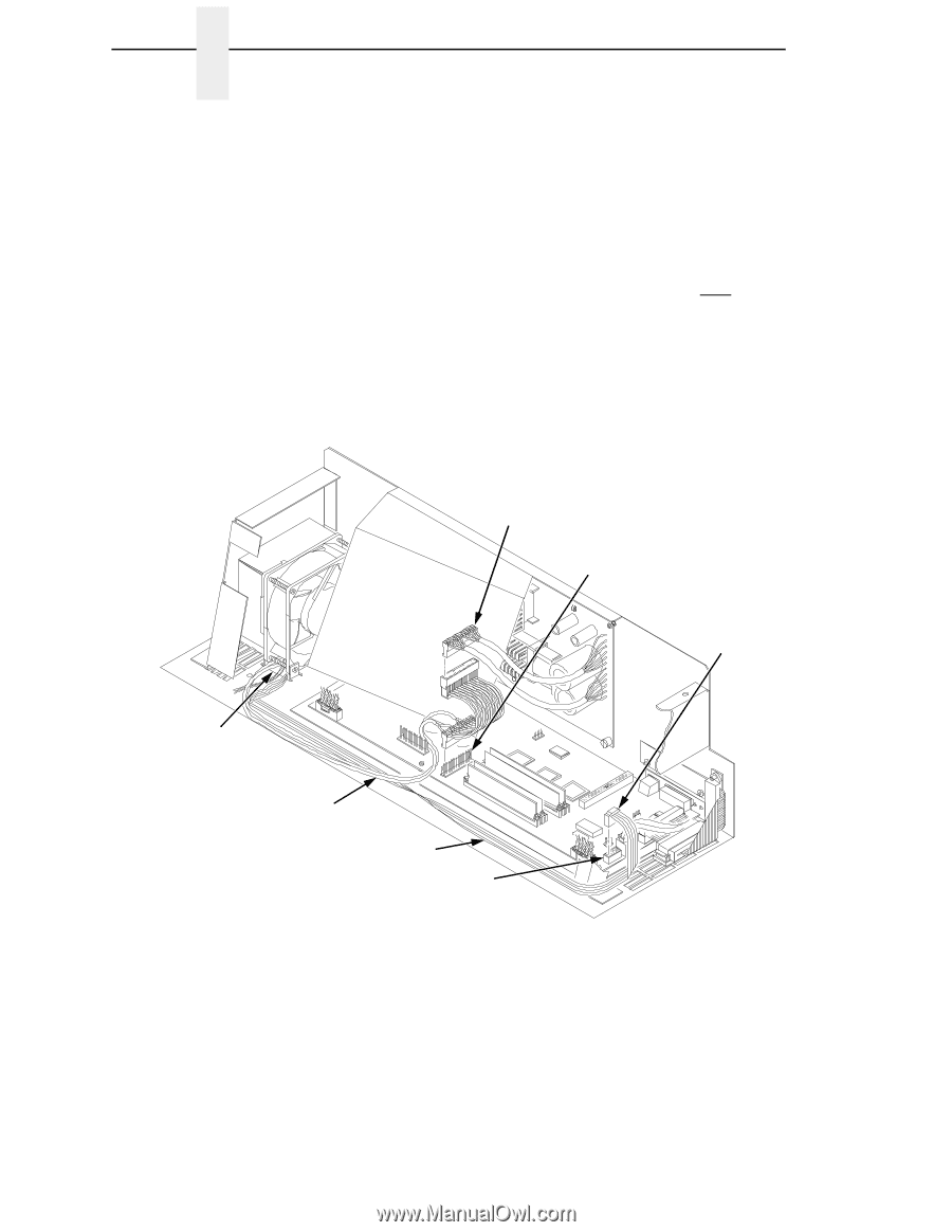
| Cleaning the Card Cage Fan Assembly |
30 |
| 1. Cabinet Models: Remove the paper path (page 161). Pedestal Models: Remove the top cover assemb... |
30 |
| 2. Vacuum the card cage fan assembly and surrounding areas to remove paper particles, dust, and l... |
30 |
| 3. Cabinet Models: Install the paper path (page 161) Pedestal Models: Install the top cover assem... |
30 |
| 4. Return the printer to normal operation (page 101). |
30 |
| 1) Card Cage Fan Assembly |
30 |
| Figure 6 . Cleaning the Card Cage Fan Assembly |
30 |
| 4 Troubleshooting |
31 |
| Introduction |
31 |
| Troubleshooting Aids |
31 |
| Start Here ... |
32 |
| Troubleshooting Display Messages |
33 |
| List of Messages |
33 |
| Table 2 . Message List |
34 |
| 1. Cycle power. If the message appears, replace the power supply board. |
34 |
| 2. Power on the printer. If the message appears, replace the CMX controller board. Record the mes... |
34 |
| 3. Power on the printer. If the message appears, replace the shuttle frame assembly. |
34 |
| 1. Cycle Power. Run the print job again. If the message appears, remove the hammer bank logic cab... |
34 |
| 2. Cycle Power. Run the print job again. If the message appears, download the emulation software ... |
34 |
| 3. Cycle power. Run the print job again. If the message appears, replace the flash memory. |
34 |
| 4. Power on the printer. Run the print job again. If the message appears, replace the CMX control... |
34 |
| 5. Check the resistance of connectors P106/LRIB M and P107/RRIB M. (Refer to the Main Wire Harnes... |
34 |
| 6. Power on the printer. Run the print job again. If the message appears, replace the power suppl... |
34 |
| 7. Power on the printer. If the message appears, replace the shuttle frame assembly. |
34 |
| 1. Cycle Power. Run the print job again. If the message appears, download the emulation software ... |
35 |
| 2. Cycle power. Run the print job again. If the message appears, replace the flash memory. |
35 |
| 3. Power on the printer. Run the print job again. If the message appears, replace the CMX control... |
35 |
| 4. Power on the printer. Run the print job again. If the message appears, replace the power suppl... |
35 |
| 5. Power on the printer. If the message appears, replace the shuttle frame assembly. |
35 |
| 1. Power off the printer. Remove the paper path or pedestal top cover. Check that power supply co... |
35 |
| 2. Power on the printer. If the message appears, replace the hammer bank logic cable assembly (P1... |
35 |
| 3. Power on the printer. If the message appears, replace the power supply board. |
35 |
| 4. Power on the printer. If the message appears, replace the CMX controller board. Record the mes... |
35 |
| 5. Power on the printer. If the message appears, replace shuttle frame assembly. |
35 |
| 1. Cycle power. Run the print job again. If the message appears, download the emulation software ... |
35 |
| 2. Cycle power. Run the print job again. If the message appears, replace the CMX controller board... |
35 |
| 1. Verify that the printer matches the host serial interface configuration settings for Data Prot... |
36 |
| 2. Send a print job to the printer. If the message appears, go to Communications Failures, page 83. |
36 |
| 1. Inspect the paper path for jams. Clear jams. Load paper. |
36 |
| 2. Press PAPER ADVANCE several times and check that forms feed without erratic motion, noise, or ... |
36 |
| 3. Press VIEW once and check that forms move up. Make sure the forms thickness lever is not set t... |
36 |
| 4. Press VIEW again and check that the forms thickness lever rotates and the paper moves down. If... |
36 |
| 5. Check the paper tension between the tractors. Adjust the right tractor so that it does not pul... |
36 |
| 6. Inspect the ribbon mask for bends or deformation. Replace if damaged. |
36 |
| 7. Check anddjust the platen open belt. Replace the belt if it is damaged. |
36 |
| 8. Bottom out the platen open motor pulley on the motor shaft and torque the 1/16 inch set screw ... |
37 |
| 9. Inspect the tractors and tractor door springs for damage or excessive wear. If either tractor ... |
37 |
| 10. Check the condition and tension of the paper feed belt. Adjust the paper feed belt. Replace t... |
37 |
| 11. Check and adjust the platen gap. |
37 |
| 12. Clean the paper motion detector with a cotton swab and alcohol. At the control panel, set the... |
37 |
| 1. Load paper. Close the forms thickness lever. |
38 |
| 2. Power off the printer. Remove the paper path or pedestal top cover. Disconnect connector P107 ... |
38 |
| 3. Tighten the screws securing the platen interlock switch |
38 |
| 4. Check and adjust the platen open belt. Replace the belt if it is damaged. |
38 |
| 5. Bottom out the platen open motor pulley on the motor shaft and torque the 1/16 inch set screw ... |
38 |
| 6. Disconnect connector P106 from the CMX controller board. Check the resistance of connector P10... |
38 |
| 7. Run a print test. If the message appears, replace the CMX controller board. Record the message... |
38 |
| 1. Advise the user to move the printer to cooler, cleaner location. |
39 |
| 2. Check the kinds of print jobs the user is running: look for very dense graphics and layouts. A... |
39 |
| 3. Power off the printer. Remove the paper path or pedestal top cover. Check all fan cable connec... |
39 |
| 4. Power on the printer. Verify that all fans operate. Replace any fan that does not operate. |
39 |
| 5. Inspect vents and fan airways for obstructions. Look underneath cabinet models for items block... |
39 |
| 6. Install the paper path or pedestal top cover. Load paper. Run the “All E’s” print test for 5 t... |
39 |
| 7. Run the “All E’s” print test for 5 to 10 minutes. If the message appears, replace the CMX cont... |
39 |
| 1. Cycle Power. Run the print job again. If the message appears, download the emulation software ... |
40 |
| 2. Cycle power. Run the print job again. If the message appears, replace the flash memory. |
40 |
| 3. Power on the printer. Run the print job again. If the message appears, replace the CMX control... |
40 |
| 4. Power on the printer. Run the print job again. If the message appears, replace the power suppl... |
40 |
| 5. Power on the printer. If the message appears, replace the shuttle frame assembly. |
40 |
| 1. Cycle power. If the message appears, press CLEAR. |
40 |
| 2. Power off the printer. Remove the shuttle cover. At the shuttle frame assembly, disconnect the... |
40 |
| 1. Replace the DRAM. |
40 |
| 2. Power on the printer. If the message appears, replace the CMX controller board. Record the mes... |
40 |
| 1. Download the program again (page 129). If the message occurs again, replace all flash memory S... |
41 |
| 2. Power on the printer. Download the emulation. If the message appears, replace the CMX controll... |
41 |
| 1. Power off the printer. Remove all flash memory and DRAM SIMMs. Inspect the SIMM sockets on the... |
41 |
| 2. Install the flash and DRAM SIMMs, making sure they are fully and correctly seated. Power on th... |
41 |
| 3. Power on the printer. Download the emulation. If the message appears, replace the DRAM SIMM(s). |
41 |
| 4. Power on the printer. Download the emulation. If the message appears, replace the CMX controll... |
41 |
| 1. Check the security PAL at location U54 on the CMX controller board. If the PAL is absent, inst... |
42 |
| 2. Power on the printer. If the message appears, replace the CMX controller board. Record the mes... |
42 |
| 1. Power off the printer. Download the program again from the beginning. If the messages appears,... |
42 |
| 2. Download the program using a new software diskette. If the messages appears, replace the flash... |
42 |
| 3. Download the program. If the messages appears, replace the CMX controller board. Record the me... |
42 |
| 1. Cycle power. If the message appears, press CLEAR. |
43 |
| 2. Check that the exhaust fan is connected to exhaust fan cable connector J307. Connect the fan c... |
43 |
| 3. Power off the printer. Remove the paper path. Disconnect connector P107 from the CMX controlle... |
43 |
| 4. Make sure connector P107/EHF has a good connection at J107 on the CMX controller board. |
43 |
| 5. Inspect for obstructions of airways and vents. Check for items beneath the printer blocking ca... |
43 |
| 6. Power on the printer. Check for fan operation. If the message appears or the fan doesn’t work,... |
43 |
| 7. Power on the printer. If the message appears, replace the CMX controller board. Record the mes... |
43 |
| 1. Cycle power. Run the print job. If the message appears, download the emulation software again ... |
44 |
| 2. Cycle power. Run the print job again. If the message appears, replace the flash memory. |
44 |
| 3. Cycle power. Run the print job again. If the message appears, replace the CMX controller board... |
44 |
| 4. Power on the printer. Run the print job again. If the message still appears, there is an appli... |
44 |
| 1. Make a configuration printout. Set printer serial interface parameters to match host configura... |
44 |
| 2. Send a print job to the printer. If the message appears, go to Communications Failures, page 83. |
44 |
| 1. Release stuck keys. Determine and correct what made the key(s) stick. |
44 |
| 2. Cycle power: power off the printer, wait 15 seconds, power on the printer. If the message appe... |
44 |
| 1. Power off the printer. Hold any control panel key down and power on the printer. Hold the key ... |
44 |
| 2. If the message reappears after doing step 1, replace the CMX controller board. Record the mess... |
44 |
| 1. Cycle power. If the message appears, replace the shuttle frame assembly. |
45 |
| 2. Power on the printer. Run a print test. If the message appears, replace the CMX controller boa... |
45 |
| 1. Cycle power. If the message appears, replace the shuttle frame assembly. Record the message an... |
45 |
| 2. Power on the printer. If the message appears, replace CMX controller board. Record the message... |
45 |
| 1. Install the shuttle frame assembly. |
45 |
| 2. Remove the paper path or pedestal top cover. Verify that the hammer bank logic cable is connec... |
45 |
| 3. Power on the printer. If the message appears, replace the hammer bank logic cable. |
45 |
| 4. Power on the printer. If the message appears, replace the shuttle frame assembly. |
45 |
| 5. Power on the printer. If the message appears, replace the CMX controller board. Record the mes... |
45 |
| 1. Cycle power. If the message appears, press CLEAR. If the message does not clear, go to step 2. |
46 |
| 2. Power off the printer. Remove the paper path or pedestal top cover. Disconnect connector P107 ... |
46 |
| 3. Make sure P107/HBF has a good connection at J107 on the CMX controller board. |
46 |
| 4. Inspect for obstructions of airways and vents. Remove obstructions. |
46 |
| 5. Power on the printer. If the message appears, replace the CMX controller board. Record the mes... |
46 |
| 1. Cycle power. Run the print job again. If the message appears, download the emulation software ... |
46 |
| 2. Cycle power. Run the print job again. If the message appears, replace the CMX controller board... |
46 |
| 1. Cycle power. Run the print job again. If the message appears, download the emulation software ... |
46 |
| 2. Cycle power. Run the print job again. If the message appears, replace the CMX controller board... |
46 |
| 1. Illegal Operand Accessed. Firmware error on the CMX controller board. |
46 |
| 1. Cycle power. Run the print job again. If the message appears, download the emulation software ... |
46 |
| 2. Cycle power. Run the print job again. If the message appears, replace the CMX controller board... |
46 |
| 1. Cycle power. If the message appears, press CLEAR. If the message does not clear, go to step 2. |
47 |
| 2. Power off the printer. Remove the paper path or pedestal top cover. Disconnect connector P106 ... |
47 |
| 3. Make sure P106/CCF has a good connection at J106 on the CMX controller board. |
47 |
| 4. Inspect for obstructions of airways and vents. Remove obstructions. |
47 |
| 5. Power on the printer. If the message appears, replace the CMX controller board. Record the mes... |
47 |
| 1. Cycle power. If this message occurred once and never again, you can ignore it. If the message ... |
47 |
| 2. Power on the printer. Cycle power. If the message appears, suspect an application software err... |
47 |
| 1. Cycle power. If the message appears, press CLEAR. If message does not clear, replace the hamme... |
47 |
| 2. Power on the printer. If the message appears, replace the shuttle frame assembly. |
47 |
| 3. Power on the printer. If the message appears, replace the CMX controller board. Record the mes... |
47 |
| 1. Load paper. Press CLEAR. If message does not clear, go to step 2. |
48 |
| 2. Power off the printer. Remove the paper path or pedestal top cover. Remove the barrier shield ... |
48 |
| 3. Check that connector P106/PMD is fully seated in connector J106 on the CMX controller board. |
48 |
| 4. Load paper. Power on the printer. Replace the paper detector switch assembly if message appears. |
48 |
| 5. Load paper. Power on the printer. Replace the CMX controller board if message appears. Record ... |
48 |
| 1. Cycle power. Run the print job again. If the message appears, download the emulation software ... |
48 |
| 2. Cycle power. Run the print job again. If the message appears, replace the CMX controller board... |
48 |
| 1. Cycle power. Run the print job again. If the message appears, download the emulation software ... |
49 |
| 2. Run the print job again. If the message appears, power off the printer. Remove the paper path ... |
49 |
| 3. Power on the printer. Run the print job again. If the message appears, replace the shuttle fra... |
49 |
| 4. Power on the printer. Run the print job again. If the message appears, replace the CMX control... |
49 |
| 1. Cycle power. Run the print job again. If the message appears, download the emulation software ... |
49 |
| 2. Power on the printer. Run the print job again. If the message appears, replace the CMX control... |
49 |
| 1. Cycle power. Run the print job again. If the message appears, download the emulation software ... |
50 |
| 2. Run the print job again. If the message appears, power off the printer. Remove the paper path ... |
50 |
| 3. Check hammer phasing. Try using a lower phasing value; sometimes this message indicates too hi... |
50 |
| 4. Power on the printer. Run the print job again. If the message appears, replace the shuttle fra... |
50 |
| 5. Power on the printer. Run the print job again. If the message appears, replace the power suppl... |
50 |
| 6. Power on the printer. Run the print job again. If the message appears, replace the CMX control... |
50 |
| 1. Cycle power. Run the print job again. If the message appears, download the emulation software ... |
50 |
| 2. Cycle power. Run the print job again. If the message appears, replace the CMX controller board... |
50 |
| 1. Cycle power. Run the print job again. If the message appears, download the emulation software ... |
50 |
| 2. Cycle power. Run the print job again. If the message appears, replace the CMX controller board... |
50 |
| 1. Cycle power. Run the print job again. If the message appears, download the emulation software ... |
51 |
| 2. Cycle power. Run the print job again. If the message appears, replace the CMX controller board... |
51 |
| 1. Cycle power. Run the print job again. If the message appears, download the emulation software ... |
51 |
| 2. Cycle power. Run the print job again. If the message appears, replace the CMX controller board... |
51 |
| 1. Cycle power. Run the print job again. If the message appears, download the emulation software ... |
51 |
| 2. Cycle power. Run the print job again. If the message appears, replace the MPU cable assembly. |
51 |
| 3. Power on the printer. Run the print job again. If the message appears, replace the power suppl... |
51 |
| 4. Power on the printer. Run the print job again. If the message appears, replace the shuttle fra... |
51 |
| 5. Power on the printer. Run the print job again. If the message appears, replace the CMX control... |
51 |
| 1. Cycle power. Run the print job again. If the message appears, download the emulation software ... |
51 |
| 2. Cycle power. Run the print job again. If the message appears, replace the CMX controller board... |
51 |
| 1. Cycle power. Run the print job again. If the message appears, download the emulation software ... |
52 |
| 2. Cycle power. Run the print job again. If the message appears, replace the CMX controller board... |
52 |
| 1. Press CLEAR then press ON LINE. |
52 |
| 2. Run the print job that generated the error message. If the message appears, check the host dat... |
52 |
| 3. Ask the system operator to verify that the printer’s Device ID is set to the correct emulation... |
52 |
| 4. Run the print job that generated the error message. If the message appears, go to Communicatio... |
52 |
| 1. Verify that the printer matches host serial configuration settings for Data Protocol, Baud Rat... |
52 |
| 2. Send a print job to the printer. If the message appears, replace the serial data cable. |
52 |
| 3. Send a print job to the printer. If the message appears, go to Communications Failures, page 83. |
52 |
| 1. Cycle power. Run the print job again. If the message appears, download the emulation software ... |
52 |
| 2. Cycle power. Run the print job again. If the message appears, replace the CMX controller board... |
52 |
| 1. Cycle power. Run the print job again. If the message appears, download the emulation software ... |
53 |
| 2. Cycle power. Run the print job again. If the message appears, replace the CMX controller board... |
53 |
| 1. Cycle power. Run the print job again. If the message appears, download the emulation software ... |
53 |
| 2. Cycle power. Run the print job again. If the message appears, replace the CMX controller board... |
53 |
| 1. Inspect printer environment for severity. Advise the user to move the printer to cooler, clean... |
54 |
| 2. Check the kinds of print jobs the user is running: look for very dense graphics and layouts. A... |
54 |
| 3. Power off the printer. Remove the paper path or pedestal top cover. Check that the power suppl... |
54 |
| 4. Check that all fan cables are connected. |
54 |
| 5. Inspect vents and fan airways for obstructions. Look underneath cabinet models for items block... |
54 |
| 6. Install paper path or pedestal top cover. Load paper. Power on the printer. Run the “All E’s” ... |
54 |
| 1. CMX controller board sensors report high temperatures on the board. Inspect printer environmen... |
55 |
| 2. Power off the printer. Remove the paper path or pedestal top cover. Check that all fan cables ... |
55 |
| 3. Inspect vents and fan airways for obstructions. Look underneath cabinet models for items block... |
55 |
| 4. Install paper path or pedestal top cover. Load paper. Power on the printer. Run the “All Black... |
55 |
| 1. Cycle power. Run the print job again. If the message appears, download the emulation software ... |
55 |
| 2. Cycle power. Run the print job again. If the message appears, replace the CMX controller board... |
55 |
| 1. Cycle power. Run the print job again. If the message appears, download the emulation software ... |
55 |
| 2. Cycle power. Run the print job again. If the message appears, replace the CMX controller board... |
55 |
| 1. Cycle power. Run the print job again. If the message appears, download the emulation software ... |
56 |
| 2. Cycle power. Run the print job again. If the message appears, replace the CMX controller board... |
56 |
| 1. Cycle power. If the message appears, power off the printer. Remove the paper path or pedestal ... |
56 |
| 2. Power on the printer. Using a screwdriver, short across the ribbon guide screws to reverse rib... |
56 |
| 1. Remove the paper path or pedestal top cover. Check that the security PAL is correctly installed. |
56 |
| 2. Install correct PAL for the customer’s emulations with the notched end facing toward the flash... |
56 |
| 3. Run a print test. If the message appears, replace the CMX controller board. Record the message... |
56 |
| 1. Cycle power. Run the print job again. If the message appears, download the emulation software ... |
57 |
| 2. Cycle power. Run the print job again. If the message appears, replace the CMX controller board... |
57 |
| 1. Cycle power. Run the print job again. If the message appears, download the emulation software ... |
57 |
| 2. Cycle power. Run the print job again. If the message appears, replace the CMX controller board... |
57 |
| 1. Set the forms thickness lever to match the thickness of paper, but not too tightly. |
58 |
| 2. Check/adjust the platen gap. |
58 |
| 3. Inspect the ribbon mask for deformation that snags and interferes with shuttle movement. Corre... |
58 |
| 4. Run a print test. If the message appears, power off the printer. |
58 |
| 5. Remove the shuttle cover and paper path or the pedestal top cover. Inspect the shuttle mechani... |
58 |
| 6. Run a print test. If the message appears, replace the power supply board. |
58 |
| 7. Run a shuttle test and observe shuttle movement. If the shuttle oscillates too slowly, adjust ... |
58 |
| 8. Run a print test. If the message appears, replace the MPU and the MPU cable assembly. |
58 |
| 9. Run a print test. If the message appears, replace the CMX controller board. Record the message... |
58 |
| 10. Run a print test. If the message appears, replace the shuttle frame assembly. |
58 |
| 1. Cycle power. If the message appears, power off the printer. |
59 |
| 2. Disconnect the input data line from the host computer. Power on the printer. If the message ap... |
59 |
| 3. Cycle power. Run the print job again. If the message appears, replace the CMX controller board... |
59 |
| 1. Cycle power. Run the print job again. If the message appears, download the emulation software ... |
59 |
| 2. Cycle power. Run the print job again. If the message appears, replace the CMX controller board... |
59 |
| 1. Cycle power. Run the print job again. If the message appears, download the emulation software ... |
59 |
| 2. Cycle power. Run the print job again. If the message appears, replace the CMX controller board... |
59 |
| 1. Power on the printer. Operate the power stacker. Check for obstructions preventing elevator mo... |
60 |
| 2. Operate the power stacker, and check that: a) all motors are operating, b) the paddles are rot... |
60 |
| 3. Adjust the stacker rails if they are not vertical and parallel. |
60 |
| 4. Check the stacker limit switches. (See page 71.) If the limit switches are OK, go to the next ... |
60 |
| 5. Disable the power stacker unit under the Printer Control menu. (Refer to the Setup Guide.) If ... |
60 |
| 6. Power off the printer. Remove the paper path. Disconnect stacker cables from the CMX controlle... |
60 |
| 1. Unload the stacker. |
61 |
| 2. Check the stacker limit switches. (See page 71.) If the limit switches are OK, go to the next ... |
61 |
| 3. Power off the printer. Remove the paper path. Disconnect stacker cables from the CMX controlle... |
61 |
| 1. Remove the paper jam. |
61 |
| 2. Power off the printer. Check that the wheel of the stacker paper motion detector rests against... |
61 |
| 3. Power on the printer. Operate the power stacker and check that: a) all motors are operating, b... |
61 |
| 4. Power off the printer. Remove the paper path. Disconnect stacker cables from the CMX controlle... |
61 |
| 1. Cycle power. Run the print job again. If the message appears, download the emulation software ... |
62 |
| 2. Cycle power. Run the print job again. If the message appears, replace the CMX controller board... |
62 |
| 1. Cycle power. Run the print job again. If the message appears, download the emulation software ... |
62 |
| 2. Cycle power. Run the print job again. If the message appears, replace the CMX controller board... |
62 |
| 1. Cycle power. Run the print job again. If the message appears, download the emulation software ... |
62 |
| 2. Cycle power. Run the print job again. If the message appears, replace the CMX controller board... |
62 |
| 1. Cycle power. If the message appears, press CLEAR. If the message does not clear, replace the h... |
62 |
| 2. Power on the printer. If the message appears, replace the CMX controller board. Record the mes... |
62 |
| 3. Power on the printer. If the message appears, replace the shuttle frame assembly. |
62 |
| Troubleshooting Other Symptoms |
64 |
| 1. Ask the operator to describe the problem. |
64 |
| 2. Verify the fault by running a diagnostic printer test or by replicating conditions reported by... |
64 |
| 3. Look for a match in the General Symptom List below. If you find a match, go to the troubleshoo... |
64 |
| 4. If you cannot find the symptom in the General Symptom List, use the Half-Split Method to find ... |
64 |
| a. Start at a general level and work down to details. |
64 |
| b. Isolate faults to half the remaining system at a time, until the final half is a field-replace... |
64 |
| 5. Replace the defective part or assembly. Do not attempt field repairs of electronic components ... |
64 |
| 6. Test printer operation after every corrective action. |
64 |
| 7. Reinstall any parts you replaced earlier that did not solve the problem. |
64 |
| 8. Stop troubleshooting and return the printer to normal operation when the reported symptoms dis... |
64 |
| General Symptom List |
65 |
| Table 3 . General Symptom List |
65 |
| 1. On 475 lpm and 500 lpm printers, check the shuttle speed (page 136). Adjust the shuttle speed ... |
65 |
| 2. Power off the printer. Remove the paper path or pedestal top cover. Remove the barrier shield ... |
65 |
| 3. Check that connector P106/PMD is fully seated in connector J106 on the CMX controller board. |
65 |
| 4. Load paper. Power on the printer. Replace the paper detector switch assembly if either message... |
65 |
| 5. Inspect the paper ironer. If the paper ironer has slipped up into the print line, reposition t... |
65 |
| 6. Load paper. Power on the printer. Replace the CMX controller board if either message appears. ... |
65 |
| 1. Remove the paper path or pedestal top cover. Make sure connector P107/PAPR M is fully seated i... |
65 |
| 2. Check the paper feed motor pulley for looseness. Hold the collar snug against the motor pulley... |
65 |
| 3. Check the condition and tension of the paper feed timing belt. Adjust the paper feed timing be... |
65 |
| 4. Load paper. Power on the printer. Press PAPER ADVANCE and VIEW several times and check that pa... |
65 |
| 5. Power on the printer. Press PAPER ADVANCE and VIEW several times and check that paper moves co... |
65 |
| 1. Power off the printer. Remove the paper path or pedestal top cover. Check that connector P106/... |
66 |
| 2. Remove the barrier shield (cabinet model) or the barrier shield and paper guide (pedestal mode... |
66 |
| 3. Check that the paper detector switch assembly is securely mounted to the mechanism base. Tight... |
66 |
| 4. Check that the motion detector wheel rotates. Replace the paper detector switch assembly if th... |
66 |
| 5. Load paper. Power on the printer. Replace the paper detector switch assembly if the message ap... |
66 |
| 6. Load paper. Power on the printer. Replace the CMX controller board if the message appears. Rec... |
66 |
| 1. Power off the printer. Remove the paper path or pedestal top cover. Disconnect the control pan... |
66 |
| 2. Power off the printer. Make sure the flash memory is seated properly in J10 and J11 on the CMX... |
66 |
| 3. Power on the printer. If black squares appear on the LCD, the flash memory could be blank. Rep... |
66 |
| 4. Power on the printer. If black squares appear on the LCD, replace the CMX controller board. Re... |
66 |
| 1. Power off the printer. Remove the paper path or pedestal top cover. Check all cable connection... |
66 |
| 2. Power on the printer. Inspect the control panel display and cooling fans. If the control panel... |
66 |
| 3. Power on the printer. If the control panel is blank and the fans do not come on, replace the C... |
66 |
| 1. Power on the printer. Check the operation of the control panel keys. Replace the control panel... |
67 |
| 2. Power on the printer. Check the operation of the control panel keys. Replace the control panel... |
67 |
| 3. Power on the printer. Check the operation of the control panel keys. Replace the CMX controlle... |
67 |
| 1. Remove the paper path or pedestal top cover. Check cable connections into the CMX controller b... |
67 |
| 2. Make sure the DRAM SIMM(s) is/are seated properly in J15/J16. Reseat DRAM SIMM(s). |
67 |
| 3. Power on the printer. Inspect the control panel display. If the control panel shows broken cha... |
67 |
| 1. Check that the AC power outlet has power. Restore AC power if necessary. |
67 |
| 2. Unplug the printer AC power cord from the printer (leave it plugged into the power outlet) and... |
67 |
| 3. Remove the paper path or pedestal top cover. Verify that the AC- In power cable and the AC pow... |
67 |
| 4. Check that AC-in power cable connector P1 is connected to J1 on the power supply board. Reseat... |
67 |
| 5. Check that power supply cable connector P101 is connected to J101 on the CMX controller board.... |
67 |
| 6. Check all cable connections on the CMX controller board. |
67 |
| 7. Disconnect AC-in power supply cable connector P1. Set the circuit breaker to 1 (on). Measure A... |
67 |
| 1. Power off the printer. Remove the paper guide or pedestal top cover. Reseat all cable connecto... |
67 |
| 2. Power up the printer. If the fans run but the printer does not initialize, replace the power s... |
67 |
| 3. Power up the printer. If the fans run but the printer does not initialize, replace the CMX con... |
67 |
| 1. Check that the power stacker is enabled under the Printer Control menu. (Refer to the Setup Gu... |
68 |
| 2. Open the rear cabinet door. Check that the ON/OFF indicator lamp is lit. If the ON/OFF indicat... |
68 |
| 3. a) Power off the printer. b) Unfasten the cable clamp holding the stacker control panel cables... |
68 |
| 4. Power off the printer. Remove the paper path. Disconnect stacker cables from the CMX controlle... |
68 |
| 5. Power on the printer. Check that the ON LINE indicator lights on the stacker control panel. If... |
68 |
| 6. Power on the printer. Check that the ON LINE indicator lights on the stacker control panel. If... |
68 |
| 1. Power off the printer. Unload paper. Open the rear cabinet door and check that stacker motion ... |
69 |
| 2. Verify that the stacker rails are vertical and parallel. Adjust the stacker rails if necessary... |
69 |
| 3. Move the elevator up and down by hand and check that the limit switches are being tripped at t... |
69 |
| 4. Power on the printer. Operate the power stacker. (Refer to the User’s Guide.) While the stacke... |
69 |
| 1. Check for and removeobstructions preventing elevator movement. |
70 |
| 2. Check for misaligned stacker rails Adjust the stacker rails if they are not vertical and paral... |
70 |
| 3. Power on the printer. Operate the power stacker. (Refer to the User’s Guide.) While the stacke... |
70 |
| 4. Check the stacker limit switches. (See page 71.) If the limit switches are OK, go to the next ... |
70 |
| 5. Check the stacker motors. (See page 72.) If the stacker motors are OK, go to the next step. |
70 |
| 6. Remove the paper path. Disconnect stacker cables from the CMX controller board, stacker assemb... |
70 |
| 1. Power off the printer. Inspect all stacker LEDs for dust, chaff, or dirt. (See Figure 81 throu... |
70 |
| 2. Power on the printer. If the stacker elevator moves by itself, replace the stacker LEDs. (See ... |
70 |
| 1. Power off the printer. Open the rear cabinet door. Unload the power stacker. Move the elevator... |
71 |
| 2. Move the elevator up and down by hand. Check that the limit switches are physically tripped wh... |
71 |
| 3. a) Unfasten the cable clamp holding the stacker control panel cables. b) Disconnect stacker ra... |
71 |
| 1. a) Power off the printer. b) Open the rear cabinet door. c) Unfasten the cable clamp holding t... |
72 |
| 1. Check the forms thickness lever: if it is set too loose or too tightly print quality can be af... |
73 |
| 2. Check the paper tension between the tractors. Adjust the right tractor so that it does not pul... |
73 |
| 3. Inspect the shuttle frame assembly for print chaff, debris, or ink residue that could be causi... |
73 |
| 4. Check the ribbon for folds or tears. Check that the ribbon guides are tight and the ribbon tra... |
73 |
| 5. Power off the printer. Remove the shuttle cover. Remove the shuttle frame assembly. Inspect th... |
73 |
| 6. Check the platen gap. Adjust the platen gap if necessary. |
73 |
| 7. Remove the paper guide assembly or pedestal top cover. Make sure Connectors P105 and P108 have... |
73 |
| 8. Power on the printer. If the problem still occurs, replace the hammer bank logic cable and the... |
73 |
| 9. Power on the printer. If the problem still occurs, replace the shuttle frame assembly. |
73 |
| 10. Power on the printer. If the problem still occurs, replace the power supply board. |
73 |
| 11. Power on the printer. If the problem still occurs, replace the CMX controller board. |
73 |
| 1. Take the printer offline and print a test pattern of All H’s. If characters shift left or righ... |
74 |
| 2. Check the hammer phasing. Adjust hammer phasing if necessary. |
74 |
| 3. If the printer is a a 500 lpm model, check the shuttle speed setting. Set the shuttle speed (p... |
74 |
| 4. Inspect the shuttle frame assembly area for ink residue, paper chaff, or debris. Clean the shu... |
74 |
| 5. Check the MPU gap. Using a feeler gauge, adjust the gap between the MPU assembly and the flywh... |
74 |
| 6. Power up the printer. Run a print test. If the symptom is not gone, replace the MPU. |
74 |
| 7. Power up the printer. Run a print test. If the symptom is not gone, replace the CMX controller... |
74 |
| 8. Power up the printer. Run a print test. If the symptom is not gone, replace the shuttle frame ... |
74 |
| 1. Power off the printer. Check the platen gap. Adjust the platen gap if necessary. |
74 |
| 2. Remove the paper guide assembly or pedestal top cover. On the left rear wall of the card cage,... |
74 |
| 3. Disconnect the AC power cord and check the ground leads for continuity. Replace the AC power c... |
74 |
| 4. Make sure the printer is plugged in to a grounded power outlet. Power up the printer. Run a pr... |
74 |
| 5. Power up the printer. Run a print test. If the problem occurs, replace the flash memory and DR... |
74 |
| 6. Power up the printer. Run a print test. If the problem occurs, replace the CMX controller board. |
74 |
| 7. Power up the printer. Run a print test. If the problem occurs, replace the power supply board. |
74 |
| 8. Power up the printer. Run a print test. If the problem occurs, replace the shuttle frame assem... |
74 |
| 1. Load paper. Press PAPER ADVANCE and check that paper feeds smoothly. Press VIEW to verify that... |
75 |
| 2. Check the paper feed motor pulley for looseness. Hold the collar snug against the motor pulley... |
75 |
| 3. Check the condition and tension of the paper feed timing belt. Adjust the paper feed timing be... |
75 |
| 4. Check the platen gap. Adjust the platen gap. |
75 |
| 5. Inspect the tractors and tractor door springs for damage or excessive wear. If either tractor ... |
75 |
| 6. Remove the paper guide assembly or pedestal top cover. Make sure connector P107/PAPR M is full... |
75 |
| 7. Load paper. Power on the printer. Run a print test. If the problem occurs, replace the paper f... |
75 |
| 8. Run a print test. If the problem occurs, replace the CMX controller board. |
75 |
| 9. Run a print test. If the problem occurs, replace the power supply board. |
75 |
| 1. Power off the printer. Remove the paper path or pedestal top cover. Check the I/O cable connec... |
76 |
| 2. Remove the flash SIMMs. Inspect the flash SIMM sockets on the CMX controller board. If any soc... |
76 |
| 3. Check that customer has the right size SIMMs for the emulation. (See page 166) Install SIMMs t... |
76 |
| 4. Power up the printer. Download the emulation (page 129). If the download fails, activate the B... |
76 |
| 5. Power up the printer. Download the emulation (page 129). If the download fails, replace the CM... |
76 |
| 1. Power off the printer. Remove the flash SIMMs. Inspect the flash SIMM sockets on the CMX contr... |
76 |
| 2. Make sure the blank SIMM is the same size as the SIMM to be copied. Install the SIMMs, making ... |
76 |
| 3. Power on the printer. From the Boot Diagnostics menu, select and run MISC UTILITIES / COPY FLA... |
76 |
| 1. Check the forms thickness lever: if it is set too tightly paper feeding can be affected. Set t... |
77 |
| 2. Power off the printer. Remove paper. Inspect the paper feed path for obstructions that could s... |
77 |
| 3. Inspect the tractors and tractor door springs for damage or excessive wear. If either tractor ... |
77 |
| 4. Check the paper feed motor pulley for looseness. Hold the collar snug against the motor pulley... |
77 |
| 5. Check the condition and tension of the paper feed timing belt. Adjust the paper feed timing be... |
77 |
| 6. Check the platen gap. Adjust the platen gap. |
77 |
| 7. Remove the paper path or pedestal top cover. Make sure connector P107/PAPR M is fully seated i... |
77 |
| 8. Load paper. Power on the printer. Press PAPER ADVANCE and VIEW several times and check that pa... |
77 |
| 9. Power on the printer. Press PAPER ADVANCE and VIEW several times and check that paper moves in... |
77 |
| 1. Remove the paper path or pedestal top cover. Reseat all cable connections to the CMX controlle... |
77 |
| 2. Power up the printer. If the printer “hangs,” replace the CMX controller board. |
77 |
| 3. Power up the printer. If the printer “hangs,” replace the power supply board. |
77 |
| 1. Check the host data cable connection at the rear of the printer. Attach the data cable to the ... |
78 |
| 2. Make a configuration printout. Verify that the printer matches host interface settings. Set pr... |
78 |
| 3. Power up the printer. Send a print job from the host. If printer does not print and the interf... |
78 |
| 4. Power up the printer. Send a print job from the host. If the printer does not print from the h... |
78 |
| 5. Remove the paper path or pedestal top cover. Check all cable connections on the CMX controller... |
78 |
| 6. Power up the printer. Send a print job from the host. If the printer still does not print from... |
78 |
| 1. Power off the printer. Remove the paper path or pedestal top cover. Disconnect the control pan... |
78 |
| 2. Connect the control panel cable assembly to J110 on the CMX controller board and to the contro... |
78 |
| 3. Power on the printer. Run a self test. If the self test does not run, replace the CMX controll... |
78 |
| 1. Raise the forms thickness lever and check that the platen opens. If the platen opens with diff... |
79 |
| 2. Check the platen open pulley and the platen pulley for looseness. Bottom out the platen open m... |
79 |
| 3. Check the condition and tension of the platen open belt. Adjust the platen open belt. Replace ... |
79 |
| 4. Check the platen gap. Adjust the platen gap. |
79 |
| 5. Power off the printer. Remove the paper guide assembly. Disconnect connector P106 from the CMX... |
79 |
| 6. Power on the printer. Press PAPER ADVANCE and VIEW several times and check that paper moves in... |
79 |
| 1. Check that the customer is setting the forms length to match the size paper used. Set the form... |
79 |
| 2. If the customer is using multi-part forms, check that the forms thickness lever is not being s... |
79 |
| 3. Check the paper feed motor pulley for looseness. Make sure the correct pulley is being used: i... |
79 |
| 4. Check the condition and tension of the paper feed timing belt. Adjust the paper feed timing be... |
79 |
| 5. Remove the paper path or pedestal top cover. Make sure connector P107/PAPR M is fully seated i... |
79 |
| 6. Power on the printer. Load paper and set TOF. Press PAPER ADVANCE and VIEW several times and c... |
79 |
| 7. Power on the printer. Press PAPER ADVANCE and VIEW several times and check that paper returns ... |
79 |
| 1. Check that both ribbon spools are fully seated on the ribbon hubs and the ribbon runs between ... |
80 |
| 2. Check that the ribbon spools are not rubbing against the shuttle cover assembly. Install the s... |
80 |
| 3. Inspect the paper print path for paper chaff, ink residue, and debris. Clean the shuttle frame... |
80 |
| 4. Power on the printer. Run a print test and observe ribbon movement across the left and right r... |
80 |
| 5. Observe ribbon movement at both left and right ribbon posts as the metal end strip crosses eac... |
80 |
| 6. While shorting across each ribbon post with the ribbon metal strip or a screwdriver, check for... |
80 |
| 7. Check the platen gap. Adjust the platen gap. |
80 |
| 1. Power down the printer. Remove the shuttle cover. Check the MPU gap. Adjust the gap between th... |
81 |
| 2. Check that the MPU cable is connected to J03 on the mechanism base. Check that the shuttle mot... |
81 |
| 3. Remove the paper path or pedestal top cover. Check that the shuttle motor drive cable is conne... |
81 |
| 4. Check the platen gap. Adjust the platen gap. |
81 |
| 5. Inspect the ribbon mask for bends or deformation that snag and interfere with shuttle movement... |
81 |
| 6. Check continuity of the shuttle motor drive cable assembly. Replace shuttle motor drive cable ... |
81 |
| 7. Power up the printer. Run a Shuttle Slow or Shuttle Fast test. If the shuttle does not move, r... |
81 |
| 8. Power up the printer. Run a Shuttle Slow or Shuttle Fast test. If the shuttle does not move, r... |
81 |
| 9. Power up the printer. Run a Shuttle Slow or Shuttle Fast test. If the shuttle does not move, r... |
81 |
| 1. Check the bolts securing the mechanism base to the base pan. Tighten the mechanism base mounti... |
82 |
| 2. Remove the shuttle cover. Check the shuttle frame assembly mounting/clamp screws for looseness... |
82 |
| 3. Inspect the shuttle area for loose hardware. Tighten loose hardware. |
82 |
| 4. Check that the hammer bank cover assembly is correctly installed, that it has not slipped off ... |
82 |
| 5. Power up the printer. Run a shuttle test. Replace the shuttle frame assembly if it is noisy or... |
82 |
| Communications Failures |
83 |
| 1. Print out the printer configuration. |
83 |
| 2. Obtain a copy of the Device Host Configuration if possible. |
83 |
| 3. Call your support group for assistance in problem analysis. |
83 |
| Table 4 . Common Communications Problems |
83 |
| Diagnostic Printer Tests |
84 |
| Selecting and Running Diagnostic Printer Tests |
85 |
| Boot Diagnostics Menu |
87 |
| Activating the Boot Diagnostics Menu |
87 |
| 1. Set the printer power switch to O (off). |
87 |
| 2. On cabinet models, raise the printer cover. |
87 |
| 3. On the control panel, press and hold down ; (PREV) + > (DOWN). |
87 |
| 4. While holding ; (PREV) + > (DOWN), set the printer power switch to 1 (on). |
87 |
| 5. When “BOOT DIAGNOSTICS / PRESS ENTER” appears on the LCD, release the ; (PREV) + > (DOWN) keys. |
87 |
| 6. Press the ENTER key. Menu options are shown in Figure 7. |
87 |
| Exiting the Boot Diagnostics Menu |
87 |
| 1. Using the directional keys, move to the MISC UTILITIES / RESET PRINTER menu option. (Refer to ... |
87 |
| 2. Press the ENTER key. |
87 |
| 1. Power off the printer. |
87 |
| 2. Wait 15 seconds. |
87 |
| 3. Power on the printer. |
87 |
| Figure 7 . Boot Diagnostics Menu |
88 |
| Hex Code Printout |
90 |
| Figure 8 . Sample Hex Dump |
90 |
| How to Print a Hex Dump |
91 |
| ASCII Character Set |
92 |
| Soft vs. Hard Reset |
93 |
| Soft Reset |
93 |
| 1. Press the ON LINE key to put the printer in the offline state. |
93 |
| 2. Press the ; (PREV) + < (NEXT) keys simultaneously. |
93 |
| Hard Reset (“Cycle Power”) |
93 |
| 1. Set the printer power switch to O (off). |
93 |
| 2. Wait 15 seconds. |
93 |
| 3. Set the printer power switch to 1 (on). |
93 |
| The Power On Sequence |
94 |
| 1. CMX controller board handshake sequences (DC hardware initialization) |
94 |
| 2. DC software initialization and power up |
94 |
| CMX Controller Board Handshake Sequences |
94 |
| DC Software Initialization and Power Up |
98 |
| 5 Adjustment Procedures |
99 |
| Introduction |
99 |
| List of Adjustments |
99 |
| Preparing the Printer for Maintenance |
100 |
| 1. Set the printer power switch to O (off). |
100 |
| 2. Unplug the printer power cord from the printer or AC power source. |
100 |
| 3. Disconnect the data (signal) cable from the printer interface. |
100 |
| 4. Open the printer cover. |
100 |
| 5. Unload paper. |
100 |
| 6. Remove the ribbon. |
100 |
| 7. Read the entire maintenance procedure before you begin working on the printer. |
100 |
| 8. Gather the necessary parts before you begin working on the printer. |
100 |
| Returning the Printer to Normal Operation |
101 |
| 1. Install the ribbon. |
101 |
| 2. Load paper. |
101 |
| 3. Connect the data (signal) cable to the printer interface. |
101 |
| 4. Plug the AC power cord into the printer and the power source. |
101 |
| 5. Close the cabinet doors. |
101 |
| 6. Set the printer power switch to | (on). |
101 |
| 7. Test printer operation by selecting and running one of the operator print tests. (See page 85.) |
101 |
| 8. Select the emulation. (Refer to the User’s Guide.) |
101 |
| 9. Set the top-of-form. (Refer to the User’s Guide.) |
101 |
| 10. Close the printer cover. |
101 |
| Belt, Paper Feed Timing, Adjustment |
102 |
| 1. Prepare the printer for maintenance (page 100). |
102 |
| 2. Cabinet Models: Remove the paper path (page 161). Pedestal Models: Remove the top cover assemb... |
102 |
| 3. Cabinet Models: Loosen four screws and remove the barrier shield. (See page 192, items 3, 4 an... |
102 |
| 4. Remove the timing belt cover (1) by squeezing the front and back to release the plastic tabs f... |
102 |
| 5. Loosen (do not remove) the two 5/16 inch motor mount bolts (2). |
102 |
| 6. Push the motor (3) toward the rear of the printer until there is 1/8 inch deflection of the be... |
102 |
| 7. Snap the timing belt cover (1) into the slots in the side plate. |
102 |
| 8. Cabinet Models: Install the barrier shield and tighten the four screws. (See page 192, items 3... |
102 |
| 9. Cabinet Models: Install the paper path (page 161). Pedestal Models: Install the top cover asse... |
102 |
| 10. Return the printer to normal operation (page 101). |
102 |
| 1) Timing Belt Shield |
103 |
| 2) Motor Mount Bolt (2) |
103 |
| 3) Paper Feed Drive Motor |
103 |
| 4) Splined Shaft |
103 |
| Figure 9 . Paper Feed Timing Belt Adjustment |
103 |
| Belt, Platen Open, Adjustment |
104 |
| 1. Prepare the printer for maintenance (page 100). |
104 |
| 2. Cabinet Models: Remove the paper path (page 161). Pedestal Models: Remove the top cover assemb... |
104 |
| 3. Remove the platen open belt cover (1) by squeezing the top and bottom to release the plastic t... |
104 |
| 4. Loosen the two 5/16 inch motor mount screws (2) enough to permit movement of the platen open m... |
104 |
| 5. Close the forms thickness lever all the way. |
104 |
| 6. Push the platen open motor toward the rear of the printer until there is 1/8 inch belt deflect... |
104 |
| 7. Snap the platen open belt cover (1) into the slots in the side plate. |
104 |
| 8. Cabinet Models: Install the paper path (page 161). Pedestal Models: Install the top cover asse... |
104 |
| 9. Return the printer to normal operation (page 101). |
104 |
| 1) Belt Cover |
105 |
| 2) Motor Mount Screw (2) |
105 |
| 3) Platen Open Motor Shaft |
105 |
| Figure 10 . Platen Open Belt Adjustment |
105 |
| Paper Drive Motor Pulley Alignment |
106 |
| 1. Prepare the printer for maintenance (page 100). |
106 |
| 2. Cabinet Models: go to step 3. Pedestal Models: Remove the top cover assembly (page 142). |
106 |
| 3. Remove the timing belt cover (1) by squeezing the front and back to release the plastic tabs f... |
106 |
| 4. Loosen the 7/64 inch screw (2) in the motor pulley collar (3). |
106 |
| 5. Align the paper drive motor pulley (4) with the splined shaft pulley (5). |
106 |
| 6. Hold the collar (3) flush against the motor pulley (4) and tighten the 7/64 inch screw (2). |
106 |
| 7. Check for correct tension on the paper feed timing belt (page 102). Adjust if necessary. |
106 |
| 8. Snap the timing belt cover (1) into the slots in the side plate. |
106 |
| 9. Cabinet Models: go to step 10. Pedestal Models: Install the top cover assembly (page 142). |
106 |
| 10. Return the printer to normal operation (page 101). |
106 |
| 1) Belt Shield |
107 |
| 2) Cap Screw |
107 |
| 3) Motor Pulley Collar |
107 |
| 4) Motor Pulley |
107 |
| 5) Splined Shaft Pulley |
107 |
| Figure 11 . Paper Drive Motor Pulley Alignment |
107 |
| Paper Scale Alignment |
108 |
| 1. Open the printer cover. |
108 |
| 2. Load paper and ribbon. |
108 |
| 3. Connect the power cord to the AC power source. |
108 |
| 4. Set the printer power switch to 1 (on). |
108 |
| 5. Verify that the shuttle cover (1) is properly installed (page 141). |
108 |
| 6. Print a full 136 column line by selecting and running one of the diagnostic self-tests. (See p... |
108 |
| 7. Check alignment of the scale to the print at column positions 1 and 136. |
108 |
| 8. If adjustment is necessary, loosen the three 5/64 inch button-head hex screws (2). |
108 |
| 9. Position the scale (3) so that column positions 1 and 136 line up with the first and last char... |
108 |
| 10. Tighten the 5/64 inch button-head hex screws (2). |
108 |
| 11. Close the printer cover. |
108 |
| 1) Shuttle Cover |
109 |
| 2) Screw, Button-Head, 5/64 inch hex (3) |
109 |
| 3) Paper Scale |
109 |
| Figure 12 . Paper Scale Alignment |
109 |
| Platen Gap Adjustment |
110 |
| 1. Prepare the printer for maintenance (page 100). |
110 |
| 2. Remove the shuttle cover assembly (page 141). |
110 |
| 3. Loosen the platen open belt (page 104, steps 2, 3, and 4). |
110 |
| 4. Raise the forms thickness lever (1) to the fully open position. |
110 |
| 5. Insert a 0.011 inch (0.28 mm) flat feeler gauge (2) straight down between the hammer bank cove... |
110 |
| 6. Gently close the forms thickness lever (1). As the platen is closing, gently slide the feeler ... |
110 |
| 7. Repeat steps 4 through 6 at the right end of the hammer bank. |
110 |
| 8. After adjusting both sides, check the gap again at both ends. Readjust if necessary. |
110 |
| 9. When the platen gap is correct at both ends of the platen, adjust the platen open belt (page 1... |
110 |
| 10. Install the shuttle cover assembly (page 141). |
110 |
| 11. Check the hammer phasing adjustment (page 121). |
110 |
| 12. Return the printer to normal operation (page 101). |
110 |
| 1) Forms Thickness Lever |
111 |
| 2) Feeler Gauge |
111 |
| 3) Hammer Bank Cover |
111 |
| 4) Ribbon Mask |
111 |
| 5) Set Screw, 3/32 inch hex (2) |
111 |
| Figure 13 . Platen Gap Adjustment |
111 |
| Platen Open Motor Pulley Alignment |
112 |
| 1. Prepare the printer for maintenance (page 100). |
112 |
| 2. Cabinet Models: Go to step 3. Pedestal Models: Remove the top cover assembly (page 142). |
112 |
| 3. Remove the platen open belt cover (1) by squeezing the top and bottom to release the plastic t... |
112 |
| 4. Loosen the 1/16 inch set screw (2) in the motor pulley. |
112 |
| 5. Bottom out the platen open motor pulley (3) on the motor shaft and tighten the 1/16 inch set s... |
112 |
| 6. Check the platen open belt tension (page 104). Adjust if necessary. |
112 |
| 7. Snap the platen open belt cover (1) into the slots in the side plate. |
112 |
| 8. Cabinet Models: Go to step 9. Pedestal Models: Install the top cover assembly (page 142). |
112 |
| 9. Return the printer to normal operation (page 101). |
112 |
| 1) Belt Cover |
113 |
| 2) Set Screw |
113 |
| 3) Platen Open Motor Pulley |
113 |
| 4) Platen Shaft Pulley |
113 |
| Figure 14 . Platen Open Motor Pulley Alignment |
113 |
| Ribbon Guide Alignment |
114 |
| 1. Open the printer cover. |
114 |
| 2. Load paper and install the ribbon. To align a ribbon guide, wind the ribbon fully onto the rib... |
114 |
| 3. Check ribbon tracking by running a ribbon and shuttle diagnostic self-test. (See Chapter 3.) |
114 |
| 4. On the ribbon guide to be adjusted, momentarily short between the ribbon guide skid screws (1)... |
114 |
| 5. Observe how the ribbon (2) passes around and across the ribbon guide. It should be centered an... |
114 |
| 6. If the ribbon is not centered, loosen the retaining screws (4) just enough so that you can rot... |
114 |
| 7. Rotate the ribbon guide as required to center the ribbon (2). |
114 |
| 8. Observe how the ribbon (2) winds onto the ribbon spool of the side you adjusted. If the ribbon... |
114 |
| 9. Tighten the retaining screws (4). |
114 |
| 10. Allow most of the ribbon to wind onto the ribbon spool on the side you adjusted, then repeat ... |
114 |
| 1) Screw, Skid (2) |
115 |
| 2) Ribbon |
115 |
| 3) White Nylon Washer |
115 |
| 4) Screw, Retaining (2) |
115 |
| Figure 15 . Ribbon Guide Alignment |
115 |
| Splined Shaft Skew Adjustment |
116 |
| 1. Open the printer cover. |
116 |
| 2. Loosen the screw (1) securing the adjusting link (2). |
116 |
| 3. Adjust the link (2) by raising or lowering the horizontal adjustment knob (3) to obtain print ... |
116 |
| 4. Return the printer to normal operation (page 101). |
116 |
| 1) Screw |
116 |
| 2) Adjusting Link |
116 |
| 3) Horizontal Adjustment Knob |
116 |
| Figure 16 . Splined Shaft Skew Adjustment |
116 |
| Paper Out Adjustment |
117 |
| 1. Open the printer cover. |
117 |
| 2. On cabinet models, open the cabinet front door. |
117 |
| 3. Load paper. Make sure the forms thickness lever is closed. |
117 |
| 4. Power on the printer. |
117 |
| 5. On the sheet of paper just below the paper entrance slot, tear a four inch square on the left ... |
117 |
| 6. If the printer is online, press the ON LINE key to place the printer offline. |
117 |
| Figure 17 . Paper Preparation for Paper Out Adjustment Test |
118 |
| 7. On the control panel, press the = + > keys to unlock the ENTER key. “ENTER SWITCH UNLOCKED” br... |
119 |
| 8. Press the ; key. “DIAGNOSTICS” displays. |
119 |
| 9. Press >. “DIAGNOSTICS / Printer Tests” displays. |
119 |
| 10. Press >. “SHIFT / RECYCLE” displays. |
119 |
| 11. Press < until “Paper Out Adjustment” displays. |
119 |
| 12. Press ENTER until the Paper Out Adjustment test starts. The comb pattern will print until the... |
119 |
| 13. Open the platen and move the paper up with the vertical position knob and examine the area of... |
119 |
| 14. Measure how short or long the comb pattern printed by counting the number of dot rows needed ... |
119 |
| 15. Close the platen. |
119 |
| 16. Press CLEAR to remove the fault condition. “OFFLINE / CONFIG. CONTROL” displays. |
119 |
| 17. Press the ; key. “DIAGNOSTICS” displays. |
119 |
| 18. Press >. “DIAGNOSTICS / Printer Tests” displays. |
119 |
| 19. Press < until “Paper Out Dots” displays. |
119 |
| 20. Press >. The top line of the display will show “Paper Out Dots” and the bottom line will show... |
119 |
| 21. Press >. The number of dots will move up to the top line of the display with an asterisk (*) ... |
120 |
| 22. Using the < or ; key, adjust the XX DOTS value up or down by the number of dots you counted i... |
120 |
| 23. Press ENTER to select the new number of dots as the active value. (The asterisk that appears ... |
120 |
| 24. Press CLEAR to place the printer offline. “OFFLINE / CONFIG. CONTROL” displays. |
120 |
| 25. Run the Paper Out Dots and the Paper Out Adjustment tests until the comb pattern prints at an... |
120 |
| 26. When the paper out triggering distance is acceptable, reload the paper, feed it past any rema... |
120 |
| 27. Press = + >. “ENTER SWITCH LOCKED” briefly displays. |
120 |
| 28. Close the printer cover. |
120 |
| 29. Press the ON LINE key to place the printer on-line. |
120 |
| Hammer Phasing Adjustment |
121 |
| 1. Raise the printer cover. |
121 |
| 2. Install the ribbon. |
121 |
| 3. Load full width (136 column) paper and set the top of form. |
121 |
| 4. Power on the printer. |
121 |
| 5. If the printer is online, press the ON LINE key to place the printer offline. “OFFLINE / CONFI... |
121 |
| 6. On the control panel, press the = + > keys to unlock the ENTER key. “ENTER SWITCH UNLOCKED” br... |
121 |
| 7. Press the ; key. “OFFLINE / DIAGNOSTICS” displays. |
121 |
| 8. Press >. “DIAGNOSTICS / Printer Tests” displays. |
121 |
| 9. Press >. “Printer Tests / Shift Recycle” displays. |
121 |
| 10. Press ; until “Printer Tests / Phase Printer” displays. |
121 |
| 11. Press ENTER. The display shows “Printer Tests / Phase Printer” and the test begins. The curre... |
121 |
| 12. Press >: The current phase index displays. Press > again: An asterisk (*) appears next to the... |
122 |
| 13. Press < to increase or ; to decrease the phasing index value, then press ENTER to activate th... |
122 |
| 14. Press = twice: “Printer Tests / Phase Printer” displays. |
122 |
| 15. Press ENTER to stop the test. |
122 |
| 16. Press CLEAR. “OFFLINE / CONFIG. CONTROL” displays. |
122 |
| 17. Press = + >. “ENTER SWITCH LOCKED” briefly displays. |
122 |
| 18. Close the printer cover. |
122 |
| 19. Press the ON LINE key to place the printer on-line. |
122 |
| Set Shuttle Speed |
123 |
| 1. Raise the printer cover. |
123 |
| 2. Power on the printer. |
123 |
| 3. If the printer is online, press the ON LINE key to place the printer offline. “OFFLINE / CONFI... |
123 |
| 4. On the control panel, press the = + > keys to unlock the ENTER key. “ENTER SWITCH UNLOCKED” br... |
123 |
| 5. Press the = + > + ; + < keys simultaneously to enter the Factory Menu. “Factory / Shuttle Spee... |
123 |
| 6. Press the > key.“Shuttle Speed / 500* ” or “Shuttle Speed / 475” appears on the display. The a... |
123 |
| 7. Press the < key until the shuttle speed you want appears on the display. |
123 |
| 8. Press the ENTER key. An asterisk [*] appears next to the selection, indicating it is now the a... |
123 |
| 9. Press the ON LINE or CLEAR key to exit the Factory Menu. |
123 |
| 10. Press the = + > keys to lock the ENTER key. “ENTER SWITCH LOCKED” briefly displays. |
123 |
| 11. Cycle printer power to activate the shuttle speed setting: set the power switch to O, wait 15... |
123 |
| 12. Adjust the hammer phasing (page 121). |
123 |
| 13. Adjust the paper out distance (page 117). |
123 |
| 14. If the printer is online, press the ON LINE key to place the printer offline. “OFFLINE / CONF... |
123 |
| 15. Print out the printer configuration. (Refer to the User’s Guide.) Verify that the configurati... |
123 |
| 16. Return the printer to normal operation (page 101). |
123 |
| 6 Replacement Procedures and Illustrated Parts Lists |
125 |
| Organization of This Chapter |
125 |
| Section I: Replacement Procedures |
126 |
| List of Removal/Installation Procedures |
126 |
| Belt, Paper Feed Timing |
128 |
| Removal |
128 |
| 1. Prepare the printer for maintenance (page 100). |
128 |
| 2. Cabinet Models: Remove the paper path (page 161). Pedestal Models: Remove the top cover assemb... |
128 |
| 3. Cabinet Models: Loosen four screws and remove the barrier shield. (See page 192, items 3, 4, a... |
128 |
| 4. Remove the timing belt cover by squeezing the front and back to release the plastic tabs from ... |
128 |
| 5. Loosen the 7/64 inch setscrew in the paper feed motor pulley collar. (See page 208, item 8.) |
128 |
| 6. Loosen (do not remove) the two 5/16 inch paper feed motor mount screws. (See page 208, item 10.) |
128 |
| 7. Remove the paper feed timing belt by sliding the paper feed motor pulley off the motor shaft a... |
128 |
| Installation |
128 |
| 1. Install the paper feed timing belt over the splined shaft pulley and the motor pulley and coll... |
128 |
| 2. Align the belt so that it will run straight on both pulleys. Tighten the two 5/ 16 inch bolts ... |
128 |
| 3. Holding a 0.040 inch feeler gauge between the pulley collar and the motor body, tighten the 7/... |
128 |
| 4. Snap the timing belt cover into the slots in the side plate. (See page 192, item 7.) |
128 |
| 5. Cabinet Models: Install the barrier shield and tighten the four screws. (See page 192, items 3... |
128 |
| 6. Cabinet Models: Install the paper path (page 161). Pedestal Models: Install the top cover asse... |
128 |
| 7. Return the printer to normal operation (page 101). |
128 |
| Belt, Platen Open |
129 |
| Removal |
129 |
| 1. Prepare the printer for maintenance (page 100). |
129 |
| 2. Cabinet Models: Remove the paper path (page 161). Pedestal Models: Remove the top cover assemb... |
129 |
| 3. Remove the platen open belt cover by squeezing the top and bottom to release the plastic tabs ... |
129 |
| 4. Loosen (do not remove) the two 5/16 inch mounting screws of the platen open motor (page 208, i... |
129 |
| 5. Push the motor toward the front of the printer to loosen the platen open belt. |
129 |
| 6. Loosen the 1/16 inch setscrew in the platen open motor pulley and remove the pulley. (See page... |
129 |
| 7. Remove the platen open belt by sliding the belt off the platen open pulley. |
129 |
| Installation |
129 |
| 1. Slide the platen open timing belt over the platen open pulley and the motor pulley. |
129 |
| 2. Slide the motor pulley onto the platen open motor shaft and tighten the 1/ 16 inch pulley sets... |
129 |
| 3. Finger tighten the two 5/16 inch screws securing the platen open motor. |
129 |
| 4. While pulling the platen open motor toward the rear, adjust the belt tension to 1/8 inch defle... |
129 |
| 5. Snap the platen open belt cover into the slots in the side plate. |
129 |
| 6. Cabinet Models: Install the paper path (page 161). Pedestal Models: Install the top cover asse... |
129 |
| 7. Return the printer to normal operation (page 101). |
129 |
| Circuit Breaker |
130 |
| Removal |
130 |
| 1. Prepare the printer for maintenance (page 100). |
130 |
| 2. Remove the card cage fan (page 148). |
130 |
| 3. Disconnect the four circuit breaker electrical leads. (Cabinet Models: See page 210. Pedestal ... |
130 |
| 4. Press in on the spring clips and remove the circuit breaker from the printer. |
130 |
| Installation |
130 |
| 1. Press the circuit breaker into the cutout until the spring clips snap into place. (Cabinet mod... |
130 |
| 2. Connect the four circuit breaker electrical leads. (Cabinet Models: See page 210. Pedestal Mod... |
130 |
| 3. Install the card cage fan (page 148). |
130 |
| 4. Return the printer to normal operation (page 101). |
130 |
| Connector Shells |
131 |
| Removal |
131 |
| 1. Prepare the printer for maintenance (page 100). |
131 |
| 2. Cabinet Models: Remove the paper path (page 161). Pedestal Models: Remove the top cover assemb... |
131 |
| 3. Remove the stiffening clip (page 133). |
131 |
| 4. Disconnect the cable connector shell containing the cable assembly that you will replace. |
131 |
| 5. Pull the side of the connector shell outward and gently pull the cable connector upward. (See ... |
131 |
| 6. Disengage the key tab(s) on the cable connector from the slots in the side of the connector sh... |
131 |
| 7. Remove the cable connector from the connector shell. (Remove only the cable connector for the ... |
131 |
| Installation |
131 |
| 1. Position the cable connector in the connector shell. Two-wire connectors are always grouped ac... |
131 |
| 2. Pull the side of the connector shell outward and gently push the cable connector down into the... |
131 |
| 3. Engage the key tab(s) on the cable connector in the slots in the side of the connector shell. ... |
131 |
| 4. Install the stiffening clip (page 133). |
131 |
| 5. Connect the cable connector shell to its printer connection. |
131 |
| 6. Cabinet Models: Install the paper path (page 161). Pedestal Models: Install the top cover asse... |
131 |
| 7. Return the printer to normal operation (page 101). |
131 |
| Figure 18 . Cable Connector Shell, Disassembly/Assembly |
132 |
| Connector Stiffening Clips |
133 |
| Removal |
133 |
| 1. Prepare the printer for maintenance (page 100). |
133 |
| 2. Cabinet Models: Remove the paper path (page 161). Pedestal Models: Remove the top cover assemb... |
133 |
| 3. Unsnap the front (open side) of the clip from the connector shell, release the back of the cli... |
133 |
| 4. Repeat step 3 for the P106 connector. |
133 |
| 5. Cabinet Models: Install the paper path (page 161). Pedestal Models: Install the top cover asse... |
133 |
| 6. Return the printer to normal operation (page 101). |
133 |
| Installation |
133 |
| 1. Prepare the printer for maintenance (page 100). |
133 |
| 2. Cabinet Models: Remove the paper path (page 161). Pedestal Models: Remove the top cover assemb... |
133 |
| 3. Work the stiffening clip over the cable bundle, engage the back of the clip under the lip of c... |
133 |
| 4. Repeat step 3 for the P106 connector. |
133 |
| 5. Cabinet Models: Install the paper path (page 161). Pedestal Models: Install the top cover asse... |
133 |
| 6. Return the printer to normal operation (page 101). |
133 |
| Figure 19 . Connector Stiffening Clips |
134 |
| Control Panel Assembly, Cabinet Models |
135 |
| Removal |
135 |
| 1. Prepare the printer for maintenance (page 100). |
135 |
| 2. Disconnect RJ11 connector P310 from connector J310 on the control panel. |
135 |
| 3. Loosen four screws securing the control panel to the control panel bracket. (See page 188, ite... |
135 |
| 4. Remove the control panel assembly from the keyways in the control panel bracket. |
135 |
| Installation |
135 |
| 1. Position the control panel assembly on the bracket, engage the mounting screws in the keyways,... |
135 |
| 2. Connect RJ11 connector P310 to connector J310 on the control panel. |
135 |
| 3. Lower the printer cover and center the control panel assembly in the cutout of the printer cover. |
135 |
| 4. Open the printer cover and tighten the four control panel mounting screws. |
135 |
| 5. Return the printer to normal operation (page 101). |
135 |
| Control Panel Assembly, Pedestal Models |
136 |
| Removal |
136 |
| 1. Prepare the printer for maintenance (page 100). |
136 |
| 2. Open the printer cover. |
136 |
| 3. Loosen the four captive screws until the control panel is released from the printer top cover.... |
136 |
| 4. Remove the two 5/16 inch screws securing the control panel ground straps. (See page 190, item ... |
136 |
| 5. Lift the control panel and disconnect the RJ11 cable connector from the control panel assembly. |
136 |
| 6. Remove the control panel assembly. |
136 |
| Installation |
136 |
| 1. Reverse steps 2 through 6 of the removal procedure. |
136 |
| 2. Return the printer to normal operation (page 101). |
136 |
| Controller Board (CMX) |
137 |
| Removal |
137 |
| 1. Make a configuration printout of all saved configurations. (Refer to the User’s Guide.) |
137 |
| 2. Prepare the printer for maintenance (page 100). |
137 |
| 3. Cabinet Models: Remove the paper path (page 161). Pedestal Models: Remove the top cover assemb... |
137 |
| 4. Disconnect all cable connectors from the controller board. (See page 198.) |
137 |
| 5. Loosen but do not remove the two screws securing the controller shield near serial cable conne... |
137 |
| 6. Loosen but do not remove the screw securing the controller shield to the bottom of the card ca... |
137 |
| 7. Slide the controller board assembly to the left until the keyway clears the screw securing the... |
137 |
| Installation |
138 |
| 1. Position the controller board in the card cage, shield side down, component side up. Engage th... |
138 |
| 2. Tighten the two screws securing the controller shield near serial cable connector J201. |
138 |
| 3. Tighten the screw securing the controller shield to the bottom of the card cage. |
138 |
| 4. Connect all cable connectors to the controller board, using the Interconnection Diagram in App... |
138 |
| 5. Cabinet Models: Install the paper path (page 161). Pedestal Models: Install the top cover asse... |
138 |
| 6. Load flash memory. (See Appendix D.) |
138 |
| 7. 500 lpm models only: set shuttle speed if the original CMX board was replaced (page 123). |
138 |
| 8. Adjust the hammer phasing (page 121). |
138 |
| 9. Adjust the paper out distance (page 117). |
138 |
| 10. Using the configuration printout(s) you made as step 1 of the removal procedure, reset and sa... |
138 |
| Cover Assembly, Hammer Bank / Ribbon Mask |
139 |
| Removal |
139 |
| 1. Prepare the printer for maintenance (page 100). |
139 |
| 2. Remove the shuttle frame assembly (page 177). |
139 |
| 3. Using a Torx T-10 driver, remove the six screws and three ribbon mask clamp plates securing th... |
139 |
| 4. Using a Torx T-10 driver, remove the 12 screws securing the hammer bank cover to the hammer ba... |
139 |
| Installation |
139 |
| 1. Position the hammer bank cover on the alignment pins on the hammer bank. Make sure the hammer ... |
139 |
| 2. Install all 12 hold-down screws finger tight. Using a Torx T-10 driver, tighten the hold-down ... |
139 |
| 3. With the seam of the folded lower edge of the ribbon mask facing inward (toward the hammer ban... |
139 |
| 4. Install the shuttle frame assembly (page 177). |
139 |
| 5. Return the printer to normal operation (page 101). |
139 |
| Figure 20 . Hammer Bank Cover Assembly / Ribbon Mask |
140 |
| Cover Assembly, Shuttle |
141 |
| Removal |
141 |
| 1. Prepare the printer for maintenance (page 100). |
141 |
| 2. Loosen the shuttle cover screws (page 192, item 2). |
141 |
| 3. Grasping the edges of the shuttle cover assembly, tilt the rear edge up and lift the shuttle c... |
141 |
| Installation |
141 |
| 1. Place the shuttle cover assembly in the printer. Tilt the forward edge of the cover down sligh... |
141 |
| 2. Tighten the shuttle cover screws (page 192, item 2). |
141 |
| 3. Return the printer to normal operation (page 101). |
141 |
| Cover Assembly, Top, Pedestal Models |
142 |
| Removal |
142 |
| 1. Prepare the printer for maintenance (page 100). |
142 |
| 2. Loosen, but do not remove, the two #2 Phillips hold-down screws on the rear of the printer. (S... |
142 |
| 3. Open the printer cover. |
142 |
| 4. Loosen the four captive #1 Phillips screws until the control panel is released from the printe... |
142 |
| 5. Loosen the two captive #2 Phillips screws in the lower front corners of the top cover. (See pa... |
142 |
| 6. Lift the top cover assembly off the printer base. |
142 |
| Installation |
142 |
| 1. Reverse steps 2 through 6 of the removal procedure. |
142 |
| 2. Return the printer to normal operation (page 101). |
142 |
| Dashpot |
143 |
| Removal |
143 |
| 1. Prepare the printer for maintenance (page 100). |
143 |
| 2. Open the cabinet rear door. |
143 |
| 3. Pry back the spring retaining clips. (See Figure 30, page 188.) |
143 |
| 4. Remove the dashpot from the ball studs. |
143 |
| Installation |
143 |
| 1. Position the dashpot against the ball studs on the upper and lower brackets. (See Figure 30, p... |
143 |
| 2. Using external grip ring pliers to spread the retaining clips, push the dashpot onto the ball ... |
143 |
| 3. Close the printer cover. |
143 |
| 4. Return the printer to normal operation (page 101). |
143 |
| Ethernet Interface Assembly |
144 |
| Removal |
144 |
| CAUTION |
144 |
| 1. Prepare the printer for maintenance (page 106). |
144 |
| 2. Cabinet Models: Remove the paper path (page 161). Pedestal Models: Remove the top cover assemb... |
144 |
| 3. Disconnect Centronics cable connector P112 from connector J112 on the CMX controller board. (S... |
144 |
| 4. Open the ferrite clamp and lift the Centronics cable out of the ferrite clamp. |
144 |
| 5. Loosen the two screws securing the LineJet Ethernet interface assembly to the cutout at the re... |
144 |
| 6. Slide the Ethernet interface assembly out of the cutout in the card cage and lift the assembly... |
144 |
| Installation |
144 |
| CAUTION |
144 |
| 1. Reverse steps 2 through 6 of the removal procedure. |
144 |
| 2. Return the printer to normal operation (page 107). |
144 |
| 10/100Base-T LEDs and DIP Switches |
145 |
| STAT (Status) Indicator in Run and Auto Reset Modes |
145 |
| Table 5 . Run Mode and Auto Reset Mode Indicator Descriptions |
145 |
| NET (Network) Indicator |
145 |
| DIP Switches |
146 |
| Table 6 . 10/100Base-T DIP Switch Settings |
146 |
| Fan Assembly, Cabinet Exhaust |
147 |
| Removal |
147 |
| 1. Prepare the printer for maintenance (page 100). |
147 |
| 2. Open the front and rear cabinet doors and the printer cover. |
147 |
| 3. Remove the paper fence/paper tray assembly. (See page 186.) |
147 |
| 4. Remove the two 1/4 inch screws securing bottom of the air exhaust duct. (See page 188, item 4). |
147 |
| 5. Remove the 1/4 inch screw directly below the forms thickness lever. |
147 |
| 6. Disconnect the fan cable connector from connector P307 and remove the air exhaust duct. |
147 |
| 7. Disconnect the fan cable connector from the side of the air exhaust duct. |
147 |
| 8. Remove the two 1/4 inch fan mounting screws and the cabinet exhaust fan assembly. |
147 |
| Installation |
147 |
| 1. Reverse steps 2 through 8 of the removal procedure. |
147 |
| 2. Return the printer to normal operation (page 101). |
147 |
| Fan Assembly, Card Cage |
148 |
| Removal |
148 |
| 1. Prepare the printer for maintenance (page 100). |
148 |
| 2. Cabinet Models: Remove the paper path (page 161). Pedestal Models: Remove the top cover assemb... |
148 |
| 3. Disconnect the card cage fan cable connector. (See page 208.) |
148 |
| 4. Cabinet Models: Remove the two fan mounting screws from the bottom of the fan. (See page 208, ... |
148 |
| 5. Remove the card cage fan assembly from the card cage. |
148 |
| Installation |
148 |
| 1. Reverse steps 2 through 5 of the removal procedure. |
148 |
| 2. Return the printer to normal operation (page 101). |
148 |
| Fan Assembly, Hammer Bank |
149 |
| Removal |
149 |
| 1. Prepare the printer for maintenance (page 100). |
149 |
| 2. Remove the shuttle cover assembly (page 141). |
149 |
| 3. Cabinet Models: Remove the paper path (page 161). Pedestal Models: Remove the top cover assemb... |
149 |
| 4. Trace the hammer bank fan cable assembly back to the controller board connector P107, releasin... |
149 |
| 5. Disconnect the fan connector from connector shell P107 on the controller board. (See page 131.) |
149 |
| 6. Remove the two screws securing the fan to the base casting. Angle the hammer bank fan assembly... |
149 |
| Installation |
149 |
| 1. Feed the hammer bank fan cable connector and motor wires between the fan well of the base cast... |
149 |
| 2. Route the fan motor wires (see cable routing diagrams, Appendix A) and connect the fan cable c... |
149 |
| 3. Install two screws in the locations shown in Figure 39 (page 208, item 21). |
149 |
| 4. Cabinet Models: Install the paper path (page 161). Pedestal Models: Install the top cover asse... |
149 |
| 5. Install the shuttle cover assembly (page 141). |
149 |
| 6. Return the printer to normal operation (page 101). |
149 |
| Hammer Spring Assembly |
150 |
| Removal |
150 |
| 1. Prepare the printer for maintenance (page 100). |
150 |
| 2. Remove the shuttle frame assembly (page 177). |
150 |
| 3. Carefully vacuum the shuttle frame assembly. |
150 |
| 4. Remove the hammer bank cover assembly (page 139). |
150 |
| 5. Remove the mounting screws from the old hammer spring assembly. (See Figure 21, page 151.) |
150 |
| 6. Handling the hammer spring assembly by the mounting base only, gently push up the mounting bas... |
150 |
| 7. Inspect the hammer bank and the old hammer spring assembly: |
150 |
| a. If there is ink on the hammer bank mounting surface, the hammer spring assembly mounting surfa... |
150 |
| b. If the old hammer spring assembly and the hammer bank are free of ink, install the new hammer ... |
150 |
| Figure 21 . Hammer Spring Assembly, Removal |
151 |
| Installation |
152 |
| 1. Using a clean dry cloth, wipe the hammer spring mounting surface on the hammer bank. Make sure... |
152 |
| 2. Handling the hammer spring assembly by the mounting base only, remove the new assembly and mou... |
152 |
| 3. Handling the hammer spring assembly by the mounting base only, carefully position the new asse... |
152 |
| 4. Install the mounting screws from the replacement kit. Using a Torx T-10 bit adapter, tighten t... |
152 |
| 5. Install the hammer bank cover assembly (page 139). |
152 |
| 6. Install the shuttle frame assembly (page 177). |
152 |
| 7. Install the ribbon and load paper. |
152 |
| 8. Run a Diagnostic Printer Test and check print quality (page 84). |
152 |
| a. If print quality is acceptable, return the printer to normal operation (page 101). |
152 |
| b. If print quality is still degraded, replace the shuttle frame assembly (page 177). |
152 |
| Figure 22 . Hammer Spring Assembly, Installation |
153 |
| Magnetic Pickup (MPU) Assembly |
154 |
| Removal |
154 |
| 1. Prepare the printer for maintenance (page 100). |
154 |
| 2. Remove the shuttle cover (page 141). |
154 |
| 3. Disconnect the magnetic pickup (MPU) cable connector (page 202, item 5). |
154 |
| 4. Loosen the 7/64 inch hex MPU clamp screw (page 202, item 3). |
154 |
| 5. Unscrew the MPU assembly from the MPU bracket. |
154 |
| Installation |
154 |
| 1. Install the MPU assembly by screwing it into the MPU bracket. (See Figure 36, page 202). |
154 |
| 2. Using a feeler gauge, adjust the gap between the MPU assembly and the flywheel to 0.010 ± .001... |
154 |
| 3. Check the gap between the MPU assembly and the flywheel with a feeler gauge: |
154 |
| a. If the gap is 0.010 ± .001 inch (0.254 ± 0.025 mm), go to step 4. |
154 |
| b. If the gap is not 0.010 ± 0.001 inch (0.254 ± 0.025 mm), loosen the MPU clamp screw and go bac... |
154 |
| 4. Route the MPU cable under the extension spring and connect the MPU cable connector (page 202, ... |
154 |
| 5. Install the shuttle cover (page 141). |
154 |
| 6. Adjust the hammer phasing (page 121). |
154 |
| 7. Return the printer to normal operation (page 101). |
154 |
| Memory Modules and Security PAL |
155 |
| Removal |
155 |
| 1. Make a configuration printout of all saved configurations. (Refer to the User’s Guide.) |
155 |
| 2. Prepare the printer for maintenance (page 100). |
155 |
| 3. Cabinet Models: Remove the paper path (page 161). Pedestal Models: Remove the top cover assemb... |
155 |
| 4. Gently pry the side locks open, angle the SIMM toward the front of the printer, and remove the... |
155 |
| 5. If the security PAL must be replaced, remove the old PAL. (See Figure 23, page 157.) The print... |
155 |
| Installation |
156 |
| 1. If you are replacing the security PAL, observe the correct pin orientation (see page 157) and ... |
156 |
| 2. Insert the memory module into the correct socket on the CMX controller board: |
156 |
| a. Position the SIMM with the notched end toward the right side of the CMX controller board. (See... |
156 |
| b. Press the SIMM into the socket with the top of the SIMM angled away from the center of the boa... |
156 |
| 3. Cabinet Models: Install the paper path (page 161). Pedestal Models: Install the top cover asse... |
156 |
| 4. Download the emulation (page 285). |
156 |
| 5. Return the printer to normal operation (page 101). |
156 |
| 6. Using the configuration printout(s) you made in step 1 of the removal procedure, reset and sav... |
156 |
| Figure 23 . Memory Modules and Security PAL |
157 |
| Paper Feed Motor |
158 |
| Removal |
158 |
| 1. Prepare the printer for maintenance (page 100). |
158 |
| 2. Cabinet Models: Remove the paper path (page 161). Pedestal Models: Remove the top cover assemb... |
158 |
| 3. Cabinet Models: Loosen four screws and remove the barrier shield. (See page 192, items 3, 4, a... |
158 |
| 4. Remove the timing belt cover by squeezing the front and back to release the plastic tabs from ... |
158 |
| 5. Loosen, but do not remove, the two 5/16 inch paper feed motor mounting screws. (See page 208, ... |
158 |
| 6. Loosen the 7/64 inch shaft collar setscrew and remove the paper feed motor pulley, shaft colla... |
158 |
| 7. Trace the paper feed motor cables back to the controller board, releasing it from tie wraps. (... |
158 |
| 8. Disconnect connector P107 from the controller board and remove the paper feed motor connector ... |
158 |
| 9. Remove the motor mount screws (and nuts, if present). |
158 |
| 10. Remove the paper feed motor assembly. |
158 |
| Installation |
159 |
| 1. Position the paper feed motor assembly on the right side plate and install the motor mount bol... |
159 |
| 2. Connect the paper feed motor cable connector to connector P107, then connect P107 to J107 on t... |
159 |
| 3. Install the collar, paper feed motor pulley, and timing belt. |
159 |
| 4. Align the paper feed motor pulley with the splined shaft pulley. |
159 |
| 5. Hold the collar snug against the motor pulley and tighten the 7/64 inch setscrew. |
159 |
| 6. While pushing the motor toward the rear of the printer, tighten the two 5/ 16 inch mounting bo... |
159 |
| 7. Snap the timing belt cover into the slots in the side plate. |
159 |
| 8. Cabinet Models: Install the barrier shield and tighten the four screws. (See page 192, items 3... |
159 |
| 9. Cabinet Models: Install the paper path (page 161). Pedestal Models: Install the top cover asse... |
159 |
| 10. Return the printer to normal operation (page 101). |
159 |
| Paper Ironer |
160 |
| Removal |
160 |
| 1. Prepare the printer for maintenance (page 100). |
160 |
| 2. Remove the shuttle frame assembly (page 177). |
160 |
| 3. Move the forms thickness lever to the open position. |
160 |
| 4. Push the ends of the paper ironer toward the rear of the printer, disengage the tabs, then lif... |
160 |
| Installation |
160 |
| 1. Position the paper ironer so the black tape is on the side that faces the rear of the printer,... |
160 |
| 2. Push the paper ironer down into the slots until the tabs engage. |
160 |
| 3. Install the shuttle frame assembly (page 177). |
160 |
| 4. Return the printer to normal operation (page 101). |
160 |
| Paper Path |
161 |
| Removal |
161 |
| 1. Prepare the printer for maintenance (page 100). |
161 |
| 2. Loosen the three paper path hold-down screws (page 192, item 6). |
161 |
| 3. Slide the paper path to the left and lift it off the card cage. |
161 |
| Installation |
161 |
| 1. Position the paper path offset slightly to the left on the card cage with the keyway cutouts o... |
161 |
| 2. Slide the paper path to the right, engaging the three hold-down screws in the keyway slots. Sl... |
161 |
| 3. Tighten the three hold-down screws (page 192, item 6). |
161 |
| 4. Return the printer to normal operation (page 101). |
161 |
| Platen |
162 |
| Removal |
162 |
| 1. Prepare the printer for maintenance (page 100). |
162 |
| 2. Remove the shuttle frame assembly (page 177). |
162 |
| 3. Remove the paper ironer (page 160). |
162 |
| 4. Remove the three 1/4 inch screws securing the paper ironer bracket assembly and remove the ass... |
162 |
| 5. Remove the platen open belt (page 129). |
162 |
| 6. Remove the platen pulley (page 206, item 21), as follows: |
162 |
| a. Loosen the 7/64 inch collar clamp screw. |
162 |
| b. Pull the platen pulley off the platen shaft. |
162 |
| 7. Pull the spring link and white plastic bushing off the platen shaft and remove the spring link... |
162 |
| 8. Remove the forms thickness lever by loosening the 7/64 inch clamp screw and pulling the lever ... |
162 |
| 9. Remove the right side platen support spring by repeating step 7 on the right side of the platen. |
162 |
| 10. Remove the Phillips #1 screw and washer securing the forms thickness indicator plate from the... |
162 |
| 11. Pull the indicator plate, with the interlock switch assembly attached, off the platen shaft. |
162 |
| 12. Remove the two 7/32 inch screws and washers securing the right ribbon guide assembly to the s... |
162 |
| 13. Slide the ribbon guide assembly out of the side plate. |
162 |
| 14. Pull the right side of the platen toward the front of the printer and move the platen to the ... |
162 |
| Installation |
163 |
| 1. Wipe the platen shafts clean of grease and debris. |
163 |
| 2. Install two washers on the longer (right) platen shaft. (See Figure 24 below.) |
163 |
| 3. Apply bearing lubricant to both platen shafts. |
163 |
| Figure 24 . Installing the Platen Adjust Bracket |
163 |
| 4. Make sure the two wear saddles are set flush into the corners of the mechanism base platen sea... |
163 |
| 5. Apply a layer of bearing lubricant 1/4 inch high to the seat of each wear saddle, making the l... |
163 |
| 6. Install one platen adjust bracket onto the longer platen shaft, with the screw at the top of t... |
163 |
| 7. Place the other bracket onto the left side mechanism base platen seat so that the mechanism ba... |
163 |
| 8. Insert the shorter platen shaft through the left adjust bracket and through the opening in the... |
163 |
| Figure 25 . Positioning the Platen Adjust Brackets |
164 |
| 9. Slide the right ribbon guide assembly into the side plate and install the two 7/32 inch screws... |
164 |
| 10. Install the forms thickness indicator plate: |
164 |
| a. Slide the indicator plate, with the interlock switch assembly attached, onto the platen shaft ... |
164 |
| b. Install the Phillips #1 screw and washer securing the indicator plate. |
164 |
| 11. Install the black metal washer onto the left side of the platen shaft. (See page 206, item 26.) |
164 |
| 12. Apply bearing lubricant to the nylon bearings in the two spring links, slide the spring links... |
164 |
| 13. Apply bearing lubricant to the two platen shafts on both sides, between the ends of the plate... |
164 |
| 14. Install the paper ironer bracket. (See Figure 24.) |
164 |
| a. With the flat part of the bracket facing the front of the printer, place the two hooks of the ... |
164 |
| b. Install and tighten the three screws. |
165 |
| 15. Push the platen to the left. |
165 |
| 16. Install the forms thickness lever onto the right side platen shaft, pressing the interlock sw... |
165 |
| 17. Install the platen shaft pulley with the 7/64 inch setscrew facing up and tighten the setscre... |
165 |
| 18. Install, but do not adjust, the platen open belt and platen open motor pulley (page 206, item... |
165 |
| 19. Install the paper ironer with the black tape towards the rear of the printer (page 206, item 3). |
165 |
| 20. Install the shuttle frame assembly (page 177). |
165 |
| 21. Adjust the platen gap (page 110). |
165 |
| 22. Adjust the platen open belt (page 104). |
165 |
| 23. Check ribbon guide alignment (page 114). |
165 |
| 24. Check the hammer phasing (page 121). |
165 |
| 25. Return the printer to normal operation (page 101). |
165 |
| Platen Open Motor |
166 |
| Removal |
166 |
| 1. Prepare the printer for maintenance (page 100). |
166 |
| 2. Cabinet Models: Remove the paper path (page 161). Pedestal Models: Remove the top cover assemb... |
166 |
| 3. Cabinet Models: Remove the card cage fan (page 148). |
166 |
| 4. Remove the platen open belt cover by squeezing the top and bottom to release the plastic tabs ... |
166 |
| 5. Loosen the two 5/16 inch motor mount screws (page 208, item 15). |
166 |
| 6. Loosen the 1/16 inch hex pulley setscrew and remove the motor pulley and platen open belt. |
166 |
| 7. Trace the platen open motor cables back to connector P106 on the controller board, releasing t... |
166 |
| 8. Remove the platen open cable connector from connector P106. (See page 132.) |
166 |
| 9. Remove the two 5/16 inch motor mount screws (and nuts, if present). |
166 |
| 10. Remove the platen open motor assembly. |
166 |
| Installation |
167 |
| 1. Position the platen open motor assembly with the wires toward the rear (page 208, item 5). |
167 |
| 2. Install the two 5/16 inch motor mount screws (and nuts, if present) finger tight. |
167 |
| 3. Install the platen open belt and motor pulley. Bottom out the motor pulley on the motor shaft ... |
167 |
| 4. Connect the platen motor cable connector to connector shell P106. |
167 |
| 5. Connect shell connector P106 to the controller board and install tie wraps to secure the motor... |
167 |
| 6. Close the forms thickness lever all the way. |
167 |
| 7. Finger tighten the two 5/16 inch screws securing the platen open motor. |
167 |
| 8. While pulling the platen open motor toward the rear of the printer, adjust the belt tension to... |
167 |
| 9. Snap the platen open belt cover into the slots in the side plate. |
167 |
| 10. Cabinet Models: Install the card cage fan (page 148). |
167 |
| 11. Cabinet Models: Install the paper path (page 161). Pedestal Models: Install the top cover ass... |
167 |
| 12. Return the printer to normal operation (page 101). |
167 |
| Power Supply Board |
168 |
| Removal |
168 |
| 1. Prepare the printer for maintenance (page 100). |
168 |
| 2. Cabinet Models: Remove the paper path (page 161). Pedestal Models: Remove the top cover assemb... |
168 |
| 3. Disconnect output connector P101 from the controller board and AC input connector P1 from the ... |
168 |
| 4. Loosen the three captive screws securing the power supply board to the rear wall of the card c... |
168 |
| 5. Carefully pry the power supply board off the three studs on the rear wall of the card cage. |
168 |
| 6. Remove the power supply board from the card cage. |
168 |
| Installation |
168 |
| 1. Reverse steps 2 through 6 of the removal procedure. |
168 |
| 2. Return the printer to normal operation (page 101). |
168 |
| Resistors, Terminating |
169 |
| Removal |
169 |
| 1. Prepare the printer for maintenance (page 100). |
169 |
| 2. Cabinet Models: Remove the paper path (page 161). Pedestal Models: Remove the top cover assemb... |
169 |
| 3. Locate the terminating resistor packs. (See Figure 26, page 170.) |
169 |
| 4. Using a chip puller, remove the resistor packs. |
169 |
| Installation |
169 |
| 1. Using a chip installation tool, install the resistor packs in the correct socket. (See Figure ... |
169 |
| 2. Cabinet Models: Install the paper path (page 161). Pedestal Models: Install the top cover asse... |
170 |
| 3. Return the printer to normal operation (page 101). |
170 |
| Figure 26 . Terminating Resistors, Removal/Installation |
170 |
| Ribbon Drive Motor |
171 |
| Removal |
171 |
| 1. Prepare the printer for maintenance (page 100). |
171 |
| 2. Remove the ribbon hub (page 173). |
171 |
| 3. Remove two screws and washers securing the ribbon drive motor to the base casting. (See page 2... |
171 |
| 4. Lift and rotate the ribbon drive motor until the motor cable is aligned with the slot on the b... |
171 |
| 5. Disconnect the ribbon drive motor cable connector. |
171 |
| 6. Remove the ribbon drive motor. |
171 |
| Installation |
171 |
| 1. Reverse steps 2 through 6 of the removal procedure above. |
171 |
| 2. Return the printer to normal operation (page 101). |
171 |
| Ribbon Guide Assembly (L/R) |
172 |
| Removal |
172 |
| 1. Prepare the printer for maintenance (page 100). |
172 |
| 2. Cut and remove the tie-wrap from the tie wrap hole to free the ribbon guide cable. (See page 2... |
172 |
| 3. Cabinet Models: Remove the paper path (page 161). Pedestal Models: Remove the top cover assemb... |
172 |
| 4. Trace the ribbon guide cable back to the controller board, releasing it from the cable restrai... |
172 |
| 5. For the left ribbon guide, disconnect connector shell P106 from the controller board. For the ... |
172 |
| 6. Trace the ribbon guide wires to the connector shell, and remove the cable connector from the c... |
172 |
| 7. Remove the two 7/32 inch screws and washers securing the ribbon guide assembly to the side pla... |
172 |
| 8. Slide the ribbon guide assembly out of the side plate. |
172 |
| Installation |
172 |
| 1. Reverse steps 2 through 8 of the removal procedure above. |
172 |
| 2. Align the ribbon guides (page 114). |
172 |
| 3. Return the printer to normal operation (page 101). |
172 |
| Ribbon Hub |
173 |
| Removal |
173 |
| 1. Prepare the printer for maintenance (page 100). |
173 |
| 2. Loosen the Torx T-10 screw in the ribbon spool hub (page 208, item 20). |
173 |
| 3. Remove the hub from the shaft of the ribbon drive motor. |
173 |
| Installation |
173 |
| 1. Install the ribbon spool hub over the motor shaft (page 208, item 20). |
173 |
| 2. Tighten the Torx T-10 hub screw so that it contacts the flat section of the motor shaft. |
173 |
| 3. Return the printer to normal operation (page 101). |
173 |
| Shaft, Splined |
174 |
| Removal |
174 |
| 1. Prepare the printer for maintenance (page 100). |
174 |
| 2. Remove the paper supports from the splined shaft and support shaft. (See page 204, item 20.) |
174 |
| 3. Remove the paper feed timing belt (page 128). |
174 |
| 4. Remove the 1/4 inch screw securing the ground clip, and remove the clip (page 204, items 10 an... |
174 |
| 5. With grip ring pliers, remove the grip ring from left side of the splined shaft (page 204, ite... |
174 |
| 6. Pull the bearing and spring link with the spring off the left side of the splined shaft (page ... |
174 |
| 7. Unlock the left and right tractors and slide them to the center of the shaft. |
174 |
| 8. Remove the 1/4 inch screw securing the bearing clamp on the right side of the splined shaft, a... |
174 |
| 9. Hold the tractors so they do not fall, grasp the vertical adjustment knob, and slide the splin... |
174 |
| Installation |
175 |
| 1. Open the doors on the left and right tractors. Position the tractor belts so the alignment mar... |
175 |
| 2. Grasp the vertical adjustment knob and slide the splined shaft through the right side plate, t... |
175 |
| 3. Install the bearing clamp and screw. |
175 |
| 4. Apply a thin film of bearing lubricant to the bearing. |
175 |
| 5. Slide the spring link and bearing onto the left side of the splined shaft with the white nylon... |
175 |
| 6. Attach the spring to the left side plate and the spring link. |
175 |
| 7. Install the grip ring on the splined shaft with 0.010 inches of clearance between the grip rin... |
175 |
| 8. Install the ground clip and screw. |
175 |
| 9. Install the paper feed timing belt (page 128). |
175 |
| 10. Set the paper feed timing belt tension (page 102). |
175 |
| 11. Adjust splined shaft skew (page 116). |
175 |
| 12. Install the paper supports on the splined shaft and support shaft. (See page 204, item 20.) |
175 |
| 13. Return the printer to normal operation (page 101). |
175 |
| Figure 27 . Splined Shaft and Tractor Installation |
175 |
| Shaft, Support |
176 |
| Removal |
176 |
| 1. Prepare the printer for maintenance (page 100). |
176 |
| 2. Unlock the tractors and slide them to the far right. |
176 |
| 3. Remove the paper supports from the splined shaft and support shaft. (See page 204, item 20.) |
176 |
| 4. Remove the E-ring (page 204, item 17). |
176 |
| 5. Slide the support shaft assembly—consisting of the support shaft, two curved washers, bushing,... |
176 |
| Installation |
176 |
| 1. Slide the support shaft assembly—consisting of the support shaft, two curved washers, bushing,... |
176 |
| 2. Slide the tractors onto the support shaft. |
176 |
| 3. Slide the support shaft assembly through the right side plate. |
176 |
| 4. Push the horizontal adjustment knob to compress the curved washers and install the E-ring in t... |
176 |
| 5. Install the paper supports to the splined shaft and support shaft. (See page 204, item 20.) |
176 |
| 6. Return the printer to normal operation (page 101). |
176 |
| Shuttle Frame Assembly |
177 |
| Removal |
177 |
| 1. Prepare the printer for maintenance (page 100). |
177 |
| 2. Remove the shuttle cover assembly (page 141). |
177 |
| 3. Disconnect the MPU cable connector P03 and shuttle motor cable connector P02 (page 202, items ... |
177 |
| 4. Disconnect the hammer drive and hammer logic cable connectors from the terminator board on the... |
177 |
| 5. Loosen the side 5/32 inch socket head clamp screws on each end of the shuttle and pull the cla... |
177 |
| 6. Loosen the center 5/32 inch socket head screw enough to release the shuttle frame assembly fro... |
177 |
| 7. Unlock and slide the tractors outward as far as they will go on the tractor support shaft. |
177 |
| 8. Open the forms thickness lever all the way. |
177 |
| 9. Grasping the support legs cast on both sides of the shuttle motor, lift the shuttle frame asse... |
177 |
| Installation |
178 |
| 1. Install the hammer bank / ribbon mask cover assembly if it was removed (page 139). |
178 |
| 2. Open the forms thickness lever and move the tractors as far left and right as possible. |
178 |
| 3. Holding the shuttle frame assembly by the support legs cast on both sides of the shuttle motor... |
178 |
| 4. Align the center 5/32 inch socket head screw in the base casting and hand turn the screw until... |
178 |
| 5. Pull the shuttle frame assembly toward the front of the printer and hold it in this position w... |
178 |
| 6. Slide the side clamps over the guide shaft and tighten the 5/32 inch socket head clamp screws. |
178 |
| 7. Tighten the center captive 5/32 inch socket head screw. |
178 |
| 8. Connect the hammer drive and hammer logic cable connectors to the terminator board on the shut... |
178 |
| 9. Connect the shuttle motor cable connector. (See page 202, item 6.) |
178 |
| 10. Route the MPU cable under the extension spring and connect the MPU cable connector. (See page... |
178 |
| 11. If the shuttle assembly is a new or refurbished unit, adjust the platen gap (page 110); other... |
178 |
| 12. Install the shuttle cover assembly (page 141). |
178 |
| 13. 500 lpm models only: set shuttle speed if original shuttle frame assembly was replaced (page ... |
178 |
| 14. Adjust the hammer phasing (page 121). |
178 |
| 15. Return the printer to normal operation (page 101). |
178 |
| Spring, Extension, Hammer Bank |
179 |
| Removal |
179 |
| 1. Prepare the printer for maintenance (page 100). |
179 |
| 2. Remove the shuttle cover assembly (page 141). |
179 |
| 3. Unhook the extension spring from the spring lugs on the hammer bank and shuttle frame. (See pa... |
179 |
| Installation |
179 |
| 1. Apply a dab of bearing lubricant to both spring lugs. |
179 |
| 2. Hook the extension spring over the spring lugs. (See page 202, item 4.) |
179 |
| 3. Install the shuttle cover assembly (page 141). |
179 |
| 4. Return the printer to normal operation (page 101). |
179 |
| Switch Assembly, Paper Detector |
180 |
| Removal |
180 |
| 1. Prepare the printer for maintenance (page 100). |
180 |
| 2. Cabinet Models: Remove the paper path (page 161). Pedestal Models: Remove the top cover assemb... |
180 |
| 3. Cabinet Models: Loosen four screws and remove the barrier shield. (See page 192, items 3, 4, a... |
180 |
| 4. Remove the two 1/4 inch screws securing the paper detector switch assembly. (See page 208, ite... |
180 |
| 5. Trace the paper detector switch cables back to controller board connector P106, removing all t... |
180 |
| 6. Disconnect connector shell P106 from the controller board (page 132). |
180 |
| 7. Trace the paper detector switch cables to the connector shell, and remove the PMD and POD cabl... |
180 |
| 8. Remove the paper detector switch assembly. |
180 |
| Installation |
180 |
| 1. Holding the slotted wheel against the PMD sensor, position the paper detector switch assembly ... |
180 |
| 2. Check PMD sensor arm range: make sure it travels freely and completely back into the sensing c... |
180 |
| 3. Route the switch cables back to the controller board connector P106. (See the cable routing di... |
180 |
| 4. Connect switch cables PMD and POD to the connector shell (page 132), then connect P106 to cont... |
180 |
| 5. Cabinet Models: Install the barrier shield and tighten the four screws. (See page 192, items 3... |
180 |
| 6. Cabinet Models: Install the paper path (page 161). Pedestal Models: Install the top cover asse... |
180 |
| 7. Check the paper out adjustment (page 117). |
180 |
| 8. Return the printer to normal operation (page 101). |
180 |
| Switch Assembly, Platen Interlock |
181 |
| Removal |
181 |
| 1. Prepare the printer for maintenance (page 100). |
181 |
| 2. Cabinet Models: Remove the paper path (page 161). Pedestal Models: Remove the top cover assemb... |
181 |
| 3. Fully close the forms thickness lever (position ‘A’). |
181 |
| 4. Trace the platen interlock switch cable back to the controller board. Remove tie-wraps as nece... |
181 |
| 5. Disconnect connector shell P107 from the controller board. |
181 |
| 6. Remove the platen interlock cable connector from the connector shell (page 132). |
181 |
| 7. Remove two Phillips #1 screws securing the platen interlock switch assembly. (See page 206, it... |
181 |
| 8. Remove the platen interlock switch assembly from the switch bracket. |
181 |
| 9. Remove the switch cable from the cutout in the right side plate. |
181 |
| Installation |
181 |
| 1. Reverse steps 2 through 9 of the removal procedure. |
181 |
| 2. Return the printer to normal operation (page 101). |
181 |
| Tractor (L/R) |
182 |
| Removal |
182 |
| 1. Prepare the printer for maintenance (page 100). |
182 |
| 2. Remove the support shaft (page 176). |
182 |
| 3. Remove the splined shaft (page 174). |
182 |
| Installation |
182 |
| 1. Using the replacement tractors, install the support shaft (page 176). |
182 |
| 2. Install the splined shaft (page 174). |
182 |
| 3. Return the printer to normal operation (page 101). |
182 |
| Section II: Illustrated Parts Lists |
183 |
| Illustrations of Printer Components |
183 |
| Figure 28 . Top Cover, Doors, and Casters |
184 |
| Figure 29 . Paper Fence and Chains |
186 |
| Figure 30 . Control Panel and Cabinet Details |
188 |
| Figure 31 . Pedestal Details |
190 |
| Figure 32 . Inside Covers, Cabinet Models |
192 |
| Figure 33 . Inside Covers and Card Cage, Pedestal Models |
194 |
| Figure 34 . Card Cage Detail, Pedestal Models |
196 |
| Figure 35 . Print Mechanism and Circuit Boards |
198 |
| Figure 36 . Magnetic Pickup (MPU) and Extension Spring |
202 |
| Figure 37 . Tractor Shafts |
204 |
| Figure 38 . Platen |
206 |
| Figure 39 . Motors, Fans, and Paper Detector Switch |
208 |
| Figure 40 . Circuit Breaker, Cabinet Models |
210 |
| Figure 41 . Ethernet Interface Assembly |
212 |
| 7 Principles of Operation |
215 |
| Line Matrix Printing |
215 |
| Figure 42 . A Dot Matrix |
215 |
| Figure 43 . Standard Character Formation |
216 |
| Figure 44 . Action of One Hammer Spring in Text Printing |
217 |
| Printing Mechanism |
218 |
| Shuttle Frame Assembly |
218 |
| Figure 45 . Shuttle Frame Assembly |
218 |
| Hammer Bank Assembly |
218 |
| Shuttle Drive Motor |
218 |
| Figure 46 . Hammer Springs and Hammer Bank (Detail) |
219 |
| Paper Transport System |
220 |
| Figure 47 . Paper Transport System |
220 |
| Ribbon Transport System |
221 |
| Figure 48 . Ribbon Transport System |
221 |
| Logical Control of the Printer |
222 |
| Figure 49 . Functional Elements of the Printer |
222 |
| Control Panel |
223 |
| Figure 50 . Control Panel Functional Overview |
223 |
| CMX Controller Board |
224 |
| Figure 51 . CMX Controller Board Block Diagram |
225 |
| Data Controller |
226 |
| 68EC030 Microprocessor |
226 |
| Flash Memory |
226 |
| DRAM |
226 |
| NVRAM |
226 |
| VX ASIC |
227 |
| Memory Access Controller |
227 |
| DRAM Controller |
227 |
| FLASH Controller |
227 |
| DMA Channels |
227 |
| Control Panel Interface |
227 |
| “Dot Plucking” and Adjacent Dot Checking |
227 |
| “Cajun” Bus Interface |
228 |
| Ports |
228 |
| Host I/O Drivers and Termination |
228 |
| Engine Controller |
229 |
| 80C166 Microprocessor |
229 |
| Bus Configuration |
229 |
| Power Reduction |
229 |
| EC Flash Memory |
229 |
| MECA ASIC |
229 |
| Analog Drive Circuitry |
229 |
| Power Supply Board |
230 |
| AC Power |
230 |
| DC Power |
231 |
| Printer Interface |
231 |
| Graphics |
232 |
| A Wire Data |
233 |
| Interconnection Diagram |
235 |
| Power Distribution Diagram |
236 |
| Main Wire Harness Test Tables |
237 |
| Controller, CMX |
238 |
| Controller (continued) |
239 |
| Controller (continued) |
240 |
| Controller (continued) |
241 |
| Power Supply |
242 |
| Power Stacker PCBA |
243 |
| Cable Routing, Cabinet Model |
244 |
| Cable Routing, Mechanism Base, Cabinet Model |
245 |
| Cable Routing, Pedestal Model |
246 |
| Cable Routing, Mechanism Base, Pedestal Model |
247 |
| Cable Assembly, Centronics I/O |
248 |
| Cable Assembly, 2-Pin Jumper, 0.1 Ctr |
249 |
| Cable Assembly, AC In, Power Supply |
250 |
| Cable Assembly, AC Power Input |
251 |
| Cable Assembly, Card Cage Fan |
252 |
| Cable Assembly, Control Panel |
253 |
| Cable Assembly, Exhaust Fan |
254 |
| Cable Assembly, Hammer Bank Logic |
255 |
| Cable Assembly, Hammer Bank Power |
256 |
| Cable Assembly, MPU |
257 |
| Ribbon Guide Kit |
258 |
| Cable Assembly, Ribbon Motor, Extension |
259 |
| Cable Assembly, Shuttle Motor Drive |
260 |
| Frame Cable, Power Stacker |
261 |
| Logic Cable, Power Stacker |
262 |
| Power Cable, Power Stacker |
263 |
| Vertical Rail Cable, Power Stacker |
264 |
| Fan Assembly, Hammer Bank |
265 |
| Magnetic Pickup (MPU) Assembly |
266 |
| Switch Assembly, Paper Detector |
267 |
| Switch Assembly, Platen Interlock |
268 |
| B Printer Specifications and Regulatory Information |
269 |
| Ribbon Specifications |
269 |
| Ribbon Life |
269 |
| Printer Dimensions |
270 |
| Environmental Characteristics |
271 |
| Temperature |
271 |
| Relative Humidity |
271 |
| ENERGY STAR® |
271 |
| Electrical Characteristics |
271 |
| Material Safety Data Sheets |
272 |
| Communication Notices |
274 |
| C Abbreviations & Signal Mnemonics |
277 |
| D Firmware Download Procedure |
285 |
| Loading Flash Memory from One Diskette |
285 |
| 1. Make a printout of all saved configurations. (Refer to the User’s Guide.) (Installing new soft... |
285 |
| 2. Set the printer power switch to O (off). |
285 |
| 3. If the printer is already connected to the serial or parallel port of a computer capable of ru... |
285 |
| 4. Unplug the AC power cord from the printer. |
285 |
| 5. Disconnect all data input cables from the printer interface. |
286 |
| 6. Connect a parallel data cable to the LPT1 port or a serial data cable to the COM1 port of an I... |
286 |
| 7. Connect the data cable to the appropriate I/O port of the printer. |
286 |
| 8. Plug the AC power cord into the printer. |
286 |
| 9. Power on the computer. |
286 |
| 10. Insert the emulation or upgrade diskette into diskette drive A (or B) of the computer. |
286 |
| 11. Make the diskette drive the active drive by typing the following at the DOS prompt: |
286 |
| 12. Get the name of the compressed file on the diskette by listing the contents of the diskette; ... |
286 |
| 13. On the printer control panel, press and hold down the ON LINE + FF keys. Without releasing th... |
286 |
| 14. When you see “WAITING FOR PROGRAM DOWNLOAD” on the LCD, release the ON LINE and FF keys. |
286 |
| 15. Press the < (NEXT) key; “SELECT DOWNLOAD PORT=DATAPRODUCT” appears on the LCD. |
286 |
| 16. Press < (NEXT) again to cycle through the download ports available in the printer: |
286 |
| 17. When the printer download port you want to use is displayed on the LCD, press ENTER. “WAITING... |
287 |
| 18. At the DOS prompt on the computer type: |
287 |
| 19. While the file is copied into memory, the printer LCD informs you of the load process and sta... |
287 |
| 20. When the new program has successfully loaded into memory and the printer has reset itself, se... |
287 |
| 21. Unplug the AC power cord from the printer. |
287 |
| 22. Remove the diskette from the computer and store it with the printer. |
287 |
| 23. Power off the computer. |
287 |
| 24. If you had to install a data cable to the computer and printer in step 6, disconnect it from ... |
287 |
| 25. Reconnect the customer’s data input cable(s) to the printer, if required. |
287 |
| 26. Return the printer to normal operation (page 101). |
287 |
| 27. Using the configuration printout(s) you made in step 1, reconfigure the printer. (Refer to th... |
287 |
| Loading Flash Memory from Multiple Diskettes |
288 |
| 1. Make a printout of all saved configurations. (Refer to the User’s Manual.) (Installing new sof... |
288 |
| 2. Set the printer power switch to O (off). |
288 |
| 3. If the printer is already connected to the serial or parallel port of a computer capable of ru... |
288 |
| 4. Unplug the AC power cord from the printer. |
288 |
| 5. Disconnect all data input cables from the printer interface. |
288 |
| 6. Connect a parallel data cable to the LPT1 port or a serial data cable to the COM1 port of an I... |
289 |
| 7. Connect the data cable to the appropriate I/O port of the printer. |
289 |
| 8. Plug the AC power cord into the printer. |
289 |
| 9. Power on the computer. |
289 |
| 10. Create a directory on your computer hard drive where you will store the recombined files from... |
289 |
| 11. Make the newly created directory the “active” directory by typing the following at the DOS pr... |
289 |
| 12. Insert the last diskette in the series (e.g., 2 of 2, 3 of 3, etc.) into diskette drive A (or... |
289 |
| 13. Get the name of the compressed file on the diskette by typing the following at the DOS prompt: |
289 |
| 14. At the DOS prompt type: |
289 |
| 15. The PKUNZIP program will execute, and the following message will appear on the computer screen: |
289 |
| 16. Remove the diskette in the disk drive and insert the diskette labeled |
289 |
| 17. Press the <Return> key. After the file is decompressed to the hard drive, the following messa... |
289 |
| 18. Remove the diskette in the disk drive and insert the diskette labeled |
289 |
| 19. Press the <Return> key. If there are only two diskettes for the emulation, you will be Return... |
289 |
| 20. When all diskettes have been decompressed, type the following at the DOS prompt: |
290 |
| 21. On the printer control panel, press and hold down the ON LINE + FF keys. Without releasing th... |
290 |
| 22. When you see “WAITING FOR PROGRAM DOWNLOAD” on the LCD, release the ON LINE and FF keys. |
290 |
| 23. Press the < (NEXT) key; “SELECT DOWNLOAD PORT=DATAPRODUCT” appears on the LCD. |
290 |
| 24. Press < (NEXT) again to cycle through the download ports available in the printer: |
290 |
| 25. When the printer download port you want to use is displayed on the LCD, press ENTER. “WAITING... |
290 |
| 26. At the DOS prompt on the computer type: |
290 |
| 27. While the file is copied into memory, the printer LCD informs you of the load process and sta... |
291 |
| 28. When the new program has successfully loaded into memory and the printer has reset itself, se... |
291 |
| 29. Unplug the AC power cord from the printer. |
291 |
| 30. Remove the diskette from the computer and store it with the printer. |
291 |
| 31. Power off the computer. |
291 |
| 32. If you had to install a data cable to the computer and printer in step 6, disconnect it from ... |
291 |
| 33. Reconnect the customer’s data input cable(s) to the printer, if required. |
291 |
| 34. Return the printer to normal operation (page 101). |
291 |
| 35. Using the configuration printout(s) you made in step 1, reconfigure the printer. (Refer to th... |
291 |
| E Host Configurations and Drivers |
293 |
| HP3000 / MPE-V |
293 |
| MPE-V Typical Configuration |
293 |
| HP3000 / MPE-XL / MPE / iX |
294 |
| MPE-XL / MPE / iX Typical Configuration |
294 |
| HP9000 / HP-UX® |
295 |
| HP-UX Typical Configuration |
295 |
| Configuration Guidelines |
295 |
| F Paper Specifications and Forms Design |
297 |
| Introduction |
297 |
| General Paper Specifications |
298 |
| Table 7 . Paper Sizes |
298 |
| Table 8 . Paper Weights |
298 |
| Paper Guidelines |
299 |
| Terms and Definitions |
299 |
| Figure 52 . Basic Forms Terminology |
300 |
| Figure 53 . Inward and Outward Perforations |
300 |
| Figure 54 . Cut Points and Tie Points |
300 |
| Environmental Considerations |
301 |
| Form Types |
301 |
| Form Weight |
301 |
| Form Thickness |
301 |
| Form Evenness |
301 |
| Tractor Pin Engagement |
301 |
| Methods of Forms Attachment |
302 |
| Gluing |
302 |
| Staples |
302 |
| Cut-to-Tie Ratio |
303 |
| Perforation Intersections |
303 |
| Chaff Content |
303 |
| Form Design Checklist |
304 |
| Environment |
304 |
| Type of Form |
304 |
| Form Weight |
304 |
| Form Thickness |
304 |
| Form Evenness |
304 |
| Tractor Pin Holes |
305 |
| Methods of Forms Attachment |
305 |
| Cut-to-Tie Ratio |
305 |
| Perforation Intersections |
306 |
| Chaff Content |
306 |
| Summary |
307 |
| Storage and Handling |
307 |
| Packaging |
307 |
| Storage |
307 |
| Preconditioning Forms |
307 |
| G Noise Suppression Devices |
309 |
| 1. Shielding Bead (P/N 141445-001PX) is a cylindrical core, through and around which the control ... |
309 |
| 2. Ferrite Clamp (P/N 202049-001PX) is a noise suppression core in a hinged plastic case and atta... |
309 |
| Figure 55 . Ferrite Core Installation |
310 |
| H Power Stacker |
311 |
| Contents |
311 |
| Introduction |
311 |
| Removing the Power Stacker |
312 |
| 1. Set the printer power switch to O (off). |
312 |
| 2. Unplug the power cord. |
312 |
| 3. Unload paper from the stacker area. (Refer to the User’s Guide.) |
312 |
| 4. Remove the paper tent. (See Figure 56.) |
312 |
| 1. Paper Tent |
312 |
| Figure 56 . Removing the Paper Tent |
312 |
| 5. Cut the tie wrap and remove the paper fence. (See Figure 57.) |
312 |
| 1. Paper Fence |
312 |
| 2. Stacker Base |
312 |
| Figure 57 . Removing the Paper Fence |
312 |
| 6. Remove three screws and washers from the stacker control panel. (See Figure 58.) |
313 |
| 1. Long Screw |
313 |
| 2. Washer |
313 |
| 3. Short Screw |
313 |
| Figure 58 . Removing the Stacker Control Panel |
313 |
| 7. Remove four cables from the stacker control panel, and remove the stacker control panel. (See ... |
313 |
| 1. Logic Cable (P104) |
313 |
| 2. Power Cable |
313 |
| 3. Frame Cable (P102) |
313 |
| 4. Rail Cable (P107) |
313 |
| Figure 59 . Removing Cables from the Stacker Control Panel |
313 |
| 8. Remove the two 5/32 x 3/4 inch screws and washers securing the vertical rails to the upper fra... |
314 |
| 9. Raise the elevator assembly. |
314 |
| 1. Vertical Rail |
314 |
| 2. Washer (2) |
314 |
| 3. Screw, 5/32 x 3/4 inch (2) |
314 |
| 4. Screw, 7/64 x 1/2 inch or Torx T-10 (2) |
314 |
| 5. Washer (2) but no washers with Torx T-10 screws |
314 |
| 6. Stacker Base |
314 |
| Figure 60 . Preparing the Stacker for Removal |
314 |
| 10. Loosen one turn—DO NOT REMOVE—the Torx T-10 screws securing the vertical rails to the stacker... |
315 |
| 1. Screw, 6-32x1/4, Torx T-10: two at bottom of each rail |
315 |
| 2. Vertical Rail |
315 |
| 3. Stacker Base |
315 |
| Figure 61 . Loosening the Lower Screws in the Vertical Rails |
315 |
| 11. Remove the 7/64 x 1/2 inch screws and washers (or Torx T-10 screws) securing the base plate t... |
315 |
| 12. Lower the elevator assembly to its lowest position. |
315 |
| 13. Slide the stacker assembly slightly to the right to clear the air exhaust duct. Tilt the vert... |
315 |
| 1. Upper Frame Cross-Member |
316 |
| 2. Elevator Assembly |
316 |
| 3. Stacker Base |
316 |
| 4. Vertical Rail |
316 |
| Figure 62 . Removing the Stacker Assembly |
316 |
| Installing the Power Stacker |
317 |
| 1. Set the printer power switch to O (off). |
317 |
| 2. Unplug the power cord. |
317 |
| 3. Remove paper. |
317 |
| 4. Loosen the three paper path hold-down screws. Slide the paper path to the left and lift it off... |
317 |
| 1. Paper Path |
317 |
| 2. Hold-Down Screw (3) |
317 |
| Figure 63 . Remove the Paper Path |
317 |
| 5. Connect the power stacker logic cable P103 to connector J17 on the CMX controller board. (See ... |
318 |
| 6. Disconnect the power supply cable from connector J101 on the CMX controller board. (See Figure... |
318 |
| 7. Connect power supply cable connector P101 to the stacker power cable, then connect the stacker... |
318 |
| 8. Route the stacker power cable and the stacker logic cable in front of the CMX board and throug... |
318 |
| 1. Power Supply Connector P101 |
318 |
| 2. CMX Board Connector J101 |
318 |
| 3. Connector P103 |
318 |
| 4. CMX Board Connector J17 |
318 |
| 5. Stacker Logic Cable |
318 |
| 6. Stacker Power Cable |
318 |
| 7. Cutout Beneath Card Cage Fan |
318 |
| Figure 64 . Stacker Power and Logic Connections on the CMX Controller Board |
318 |
| 9. Loosen one turn—DO NOT REMOVE—the Torx T-10 screws securing the vertical rails to the stacker ... |
319 |
| 1. Screw, 6-32x1/4, Torx T-10 |
319 |
| 2. Vertical Rail |
319 |
| 3. Stacker Base |
319 |
| Figure 65 . Loosening the Lower Screws in the Vertical Rails |
319 |
| 10. Position the elevator assembly at the bottom of the vertical rails. (See Figure 66a.) |
320 |
| 11. Position the stacker assembly slightly to the right in order to clear the air exhaust duct, i... |
320 |
| 12. Work the stacker base rearward and engage the upper brackets of the vertical rails under the ... |
320 |
| 13. Align the holes in the vertical rail brackets with the holes in the upper frame cross-member.... |
320 |
| 1. Upper Frame Cross-Member |
321 |
| 2. Elevator Assembly |
321 |
| 3. Stacker Base |
321 |
| 4. Vertical Rail |
321 |
| Figure 66 . Stacker Installation |
321 |
| 14. Align the holes in the stacker base with the holes in the cabinet floor. (See Figure 66c and ... |
322 |
| 15. Install finger tight the two 5/32 x 3/4 inch screws and washers securing the vertical rails t... |
322 |
| 16. Install and tighten the 7/64 x 1/2 inch screws and washers (or Torx T-10 screws) securing the... |
322 |
| 17. Move the elevator assembly up and down on the vertical rails until it travels smoothly with n... |
322 |
| 18. Tighten the two 5/32 x 3/4 inch screws and washers securing the vertical rails to the upper f... |
322 |
| 19. Move the elevator assembly up and down again to make sure it travels smoothly with no binding. |
322 |
| 20. Tighten the screws securing the vertical rails to the stacker base. Each rail is secured by t... |
322 |
| 21. Move the elevator assembly up and down to make sure it travels smoothly with no binding. If t... |
322 |
| 1. Washer (2) |
323 |
| 2. Screw, 5/32 x 3/4 inch (2) |
323 |
| 3. Stacker Base |
323 |
| 4. Screw, 7/64 x 1/2 inch or Torx T-10 (2) |
323 |
| 5. Washer (2) but no washers with Torx T-10 screws |
323 |
| 6. Vertical Rail |
323 |
| 7. Upper Frame Cross-Member |
323 |
| Figure 67 . Stacker Fasteners |
323 |
| 22. Install the paper fence. (See Figure 68.) |
324 |
| 1. Paper Fence |
324 |
| 2. Stacker Base |
324 |
| Figure 68 . Paper Fence |
324 |
| 23. Gather the rail cable, frame cable, logic cable, and power cable. Route the cables outboard o... |
325 |
| 24. Connect the stacker cables to the rear of the stacker control panel assembly, as shown in Fig... |
325 |
| 1. Logic Cable (P104) |
325 |
| 2. Power Cable |
325 |
| 3. Frame Cable (P102) |
325 |
| 4. Rail Cable (P107) |
325 |
| Figure 69 . Stacker Control Panel Cables |
325 |
| 25. Position the stacker control panel as shown in Figure 70, and install the mounting screws. |
326 |
| 1. Stacker Control Panel |
326 |
| 2. Long Screw |
326 |
| 3. Short Screw (2) |
326 |
| Figure 70 . Installing the Stacker Control Panel |
326 |
| 26. Bundle the stacker control panel cables in the wire harness clips located under the card cage... |
327 |
| 1. Wire Saddle (2) |
327 |
| 2. Cutout Beneath Card Cage Fan |
327 |
| 3. Cable Bundle |
327 |
| Figure 71 . Securing Stacker Cables |
327 |
| 27. Install the paper path that you removed in step 4. |
327 |
| 28. Install paper and test stacker operation. (Refer to the User’s Guide.) |
327 |
| Replacing the Constant Force Spring |
328 |
| 1. Remove the stacker assembly from the printer. (See page 312.) |
328 |
| 2. Raise the elevator assembly to its highest position and secure it to the vertical rails using ... |
328 |
| 1. Tie Wrap |
328 |
| 2. Elevator Assembly |
328 |
| Figure 72 . Securing the Elevator Assembly |
328 |
| 3. Remove the shoulder screw, washers, and spacer from the constant force spring and drum. Let th... |
329 |
| 4. Firmly gripping the spring and drum, remove the screw securing the spring to the vertical rail... |
329 |
| 1. Rail Screw |
329 |
| 2. Washer |
329 |
| 3. Constant Force Spring |
329 |
| 4. Large Washer |
329 |
| 5. Spacer |
329 |
| 6. Drum |
329 |
| 7. Shoulder Screw |
329 |
| Figure 73 . Removing the Constant Force Spring |
329 |
| 5. Lift the loose end of the constant force spring and let it curl up on the outside of the remai... |
330 |
| 6. While holding the drum tightly, continue to curl the spring until it is completely unwound fro... |
330 |
| 7. To install a new constant force spring, reverse the steps of this procedure. |
330 |
| 1. Spring |
330 |
| 2. Drum |
330 |
| Figure 74 . Removing the Constant Force Spring from the Drum |
330 |
| Replacing the Timing Belts |
331 |
| 1. Remove the stacker assembly from the printer. (See page 312.) |
331 |
| 2. Raise the elevator assembly to its highest position and secure it to the vertical rails using ... |
331 |
| 3. If you are removing the left timing belt, remove the shoulder screw from the pulley at the bot... |
331 |
| 4. If you are removing the right timing belt, remove the two metric Allen screws that secure the ... |
331 |
| 1. Metric Allen Screw and Washer |
331 |
| 2. Right Vertical Rail |
331 |
| 3. Timing Belt Motor |
331 |
| 4. Stacker Base |
331 |
| 5. Bushing |
331 |
| 6. Pulley |
331 |
| 7. Shoulder Screw |
331 |
| 8. Left Vertical Rail |
331 |
| Figure 75 . Removing the Timing Belt Pulley and Motor |
331 |
| 5. Loosen the two setscrews on the motor pulley and remove the pulley. Unplug the motor cable, if... |
332 |
| 1. Timing Belt Motor |
332 |
| 2. Setscrew |
332 |
| 3. Pulley |
332 |
| Figure 76 . Removing the Timing Belt Motor Pulley |
332 |
| 6. Remove the shoulder screw, washers, and spacer that secures the constant force spring to the v... |
332 |
| 1. Large Washer |
332 |
| 2. Spacer |
332 |
| 3. Constant Force Spring |
332 |
| 4. Shoulder Screw |
332 |
| Figure 77 . Releasing the Constant Force Spring |
332 |
| 7. Remove two Allen screws from the belt clamp that secures the timing belt to the stacker frame.... |
333 |
| 1. Allen Screw |
333 |
| 2. Belt Clamp |
333 |
| Figure 78 . Removing the Belt Clamps |
333 |
| 8. Remove the timing belt by working it around the vertical rail and constant force spring. (See ... |
334 |
| 1. Timing Belt |
334 |
| Figure 79 . Removing the Timing Belt |
334 |
| 9. To install a timing belt, reverse the steps of this procedure. |
334 |
| Illustrated Parts Breakdown |
335 |
| Figure 80 . Stacker Assembly |
336 |
| Figure 81 . Elevator Detail: Motor, Roller, and Paddle Assemblies |
338 |
| Figure 82 . Stacker Detail: Rollers |
340 |
| Figure 83 . Stacker Detail: Motor Bracket |
342 |
| Figure 84 . Stacker Detail: Elevator Bracket |
344 |
| Figure 85 . Stacker Detail: Paper Motion Detector |
346 |
| Numerics |
349 |
| A |
349 |
| B |
349 |
| C |
349 |
| D |
350 |
| E |
350 |
| F |
351 |
| G |
351 |
| H |
351 |
| I |
351 |
| K |
351 |
| L |
351 |
| M |
351 |
| N |
352 |
| O |
352 |
| P |
352 |
| R |
353 |
| S |
354 |
| T |
354 |
| U |
355 |
| V |
355 |
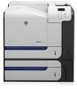
 1
1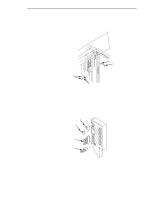 313
313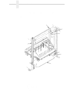 314
314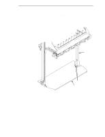 315
315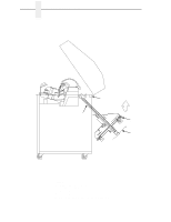 316
316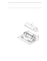 317
317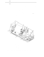 318
318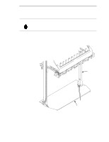 319
319 320
320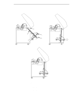 321
321 322
322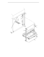 323
323