HP ML370 HP ProLiant ML370 Generation 3 Setup and Installation Guide - Page 152
Connecting the Power Cord and Peripheral Devices, Power Cord Guidelines
 |
UPC - 613326765616
View all HP ML370 manuals
Add to My Manuals
Save this manual to your list of manuals |
Page 152 highlights
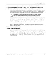
Installing the Tower Server Connecting the Power Cord and Peripheral Devices After all internal hardware options have been installed in the server, connect external power supplies and peripheral devices to the connectors located on the rear panel of the server. Icons on the back of the server identify the function of each connector. WARNING: To reduce the risk of electrical shock or fire, do not plug telecommunications/telephone connectors into the NIC receptacles. IMPORTANT: If the Remote Insight Lights-Out Edition II (RILOE II) board is installed in the server, be sure that you connect the video cable to the video connector on the rear of the RILOE II board. The standard video connector on the server rear panel is not used when the RILOE II board is installed. Refer to "Rear Panel Components" in Chapter 3 to identify connectors on the rear panel of the tower server. Power Cord Guidelines Connect the power cords provided with the server or hot-plug power supply option to each AC power supply and use the power cord retaining clips to secure the AC power cords. Leave a service loop for the plug to prevent the plug from accidentally being disengaged. Refer to Chapter 4, "Installing the Rack Server," for additional power cord instructions. HP ProLiant ML370 Generation 3 Server Setup and Installation Guide 5-3
-
 1
1 -
2
-
3
-
4
-
5
-
6
-
7
-
8
-
9
-
10
-
11
-
12
-
13
-
14
-
15
-
16
-
17
-
18
-
19
-
20
-
21
-
22
-
23
-
24
-
25
-
26
-
27
-
28
-
29
-
30
-
31
-
32
-
33
-
34
-
35
-
36
-
37
-
38
-
39
-
40
-
41
-
42
-
43
-
44
-
45
-
46
-
47
-
48
-
49
-
50
-
51
-
52
-
53
-
54
-
55
-
56
-
57
-
58
-
59
-
60
-
61
-
62
-
63
-
64
-
65
-
66
-
67
-
68
-
69
-
70
-
71
-
72
-
73
-
74
-
75
-
76
-
77
-
78
-
79
-
80
-
81
-
82
-
83
-
84
-
85
-
86
-
87
-
88
-
89
-
90
-
91
-
92
-
93
-
94
-
95
-
96
-
97
-
98
-
99
-
100
-
101
-
102
-
103
-
104
-
105
-
106
-
107
-
108
-
109
-
110
-
111
-
112
-
113
-
114
-
115
-
116
-
117
-
118
-
119
-
120
-
121
-
122
-
123
-
124
-
125
-
126
-
127
-
128
-
129
-
130
-
131
-
132
-
133
-
134
-
135
-
136
-
137
-
138
-
139
-
140
-
141
-
142
-
143
-
144
-
145
-
146
-
 147
147 -
 148
148 -
 149
149 -
 150
150 -
 151
151 -
 152
152 -
 153
153 -
 154
154 -
 155
155 -
 156
156 -
 157
157 -
158
-
159
-
160
-
161
-
162
-
163
-
164
-
165
-
166
-
167
-
168
-
169
-
170
-
171
-
172
-
173
-
174
-
175
-
176
-
177
-
178
-
179
-
180
-
181
-
182
-
183
-
184
-
185
-
186
-
187
-
188
-
189
-
190
-
191
-
192
-
193
-
194
-
195
-
196
-
197
-
198
-
199
-
200
-
201
-
202
-
203
-
204
-
205
-
206
-
207
-
208
-
209
-
210
-
211
-
212
-
213
-
214
-
215
-
216
-
217
-
218
-
219
-
220
-
221
-
222
-
223
-
224
-
225
-
226
-
227
-
228
-
229
-
230
-
231
-
232
-
233
-
234
-
235
-
236
-
237
-
238
-
239
-
240
-
241
-
242
-
243
-
244
-
245
-
246
-
247
-
248
-
249
-
250
-
251
-
252
-
253
-
254
-
255
-
256
-
257
-
258
-
259
-
260
-
261
-
262
-
263
 |
 |