HP MSA 2040 HP MSA/P2000 Controller Module Replacement Instructions (718625-00 - Page 1
HP MSA 2040 Manual
 |
View all HP MSA 2040 manuals
Add to My Manuals
Save this manual to your list of manuals |
Page 1 highlights
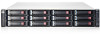
HP MSA/P2000 Controller Module Replacement Instructions Abstract This document details procedures for replacing a failed controller module in an HP Modular Smart Array system. © Copyright 2013 Hewlett-Packard Development Company, L.P. Printed in the US. HP Part Number: 718625-001 Published: June 2013 Edition: 1 *718625-001* About this document • The Storage Management Utility (SMU) and the Command Line Interface (CLI) can be used to manage the enclosure. Tasks in this document demonstrate using the SMU. • For the latest product documentation, see the HP Support Center website (http://www.hp.com/go/ hpsc). • WARRANTY STATEMENT: To obtain a copy of the warranty for this product, see the warranty information website (http://www.hp.com/go/ storagewarranty). Before you begin Observe the following: CAUTION: • Removing a module from an operational enclosure significantly changes air flow within the enclosure. Openings must be populated for the enclosure to cool properly. Leave modules in the enclosure until a replacement is available. • Parts can be damaged by electrostatic discharge; use proper anti-static protection. Keep parts in electrostatic containers until needed and ensure you are properly grounded when touching static-sensitive components. IMPORTANT: When replacing both controllers in an operational enclosure, do as follows: 1. Replace one controller as detailed in these instructions. 2. Wait 30 minutes. This pause ensures that the controller and its ownership of the vdisks has enough time to fully stabilize. 3. Check the system status and event logs to ensure that the system is stable. 4. Replace the other controller as detailed in these instructions. IMPORTANT: When two controllers are installed in an enclosure, they must be the same model. Mixing controller types in the same enclosure is not supported. To reduce the impact on system performance, perform all maintenance tasks during periods of low system activity or during a system maintenance window. The following illustration shows controller module locations. 1. Controller module A 2. Controller module B NOTE: Illustrations in this document show generic representations of modules and enclosures; procedures are the same for all modules shipped with this document. Verifying module failure Before replacing the module, look at the event log, software management utilities, and device LEDs, to confirm that the module has failed. Table 1 LED descriptions Module LED FRU OK Description • Solid Green = Module is operating normally • Blink = System is starting up • Off = Module is not operating normally Fault/Service Required • Solid Amber = Fault condition • Blinking Amber = Hardware-controlled power-up or cache flush/restore error • Off = No fault conditions Recording configuration settings As a best practice, record system settings before replacing a controller module. Page 1 To obtain key settings using the SMU, from the Configuration View panel, select the system and then click the following menu options: • For date, time, and NTP settings: Configuration > System Settings > Date, Time • For system information (name, contact, location, and description): Configuration > System Settings > System Information • For user information: Configuration > Users > Modify User • For email notification settings: Configuration > Services > Email Notification • For SNMP notification settings: Configuration > Services > SNMP Notification • For syslog notification settings: Configuration > Services > Syslog Notification • For information about scheduled tasks: View > Overview In the main panel, select Schedules. Scroll down to see details. • For information about all hosts (IDs and names): From the Configuration View panel, select Hosts. • For information about a specific host (IDs, names, and mappings): From the Configuration View panel, expand the display under Hosts and then select a specific host. ◦ For overview information (including host IDs and nicknames) in the main panel, select Host. Scroll down to see details. ◦ For mapping information, in the main panel, select Maps. Scroll down to see details. Enabling Partner Firmware Update (dual-controller configurations only) In a dual-controller configuration, the Partner Firmware Update option ensures that both controllers have the most recent version. HP recommends enabling this feature. To view or change the current Partner Firmware Update setting, select the system in the Configuration View panel and then select Configuration > Advanced Settings > Firmware. If needed, check the box and click Apply.
-
 1
1 -
 2
2
 |
 |
