HP Mini 730 HP Mini 1000 and Compaq Mini 700 - Maintenance and Service Guide - Page 65
Heat sink assembly, Hard drive or solid-state drive see
 |
View all HP Mini 730 manuals
Add to My Manuals
Save this manual to your list of manuals |
Page 65 highlights
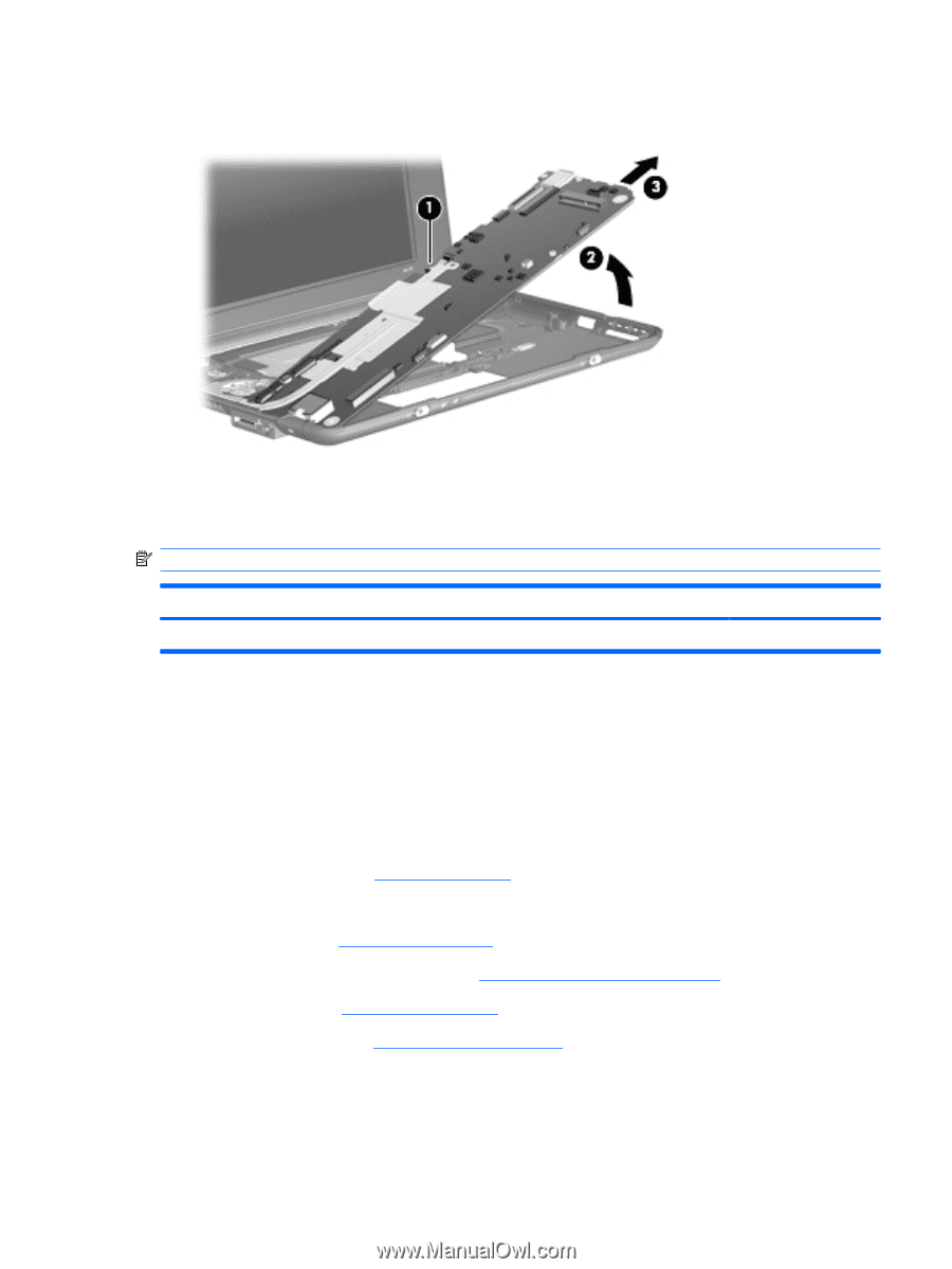
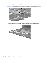
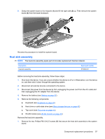
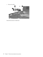
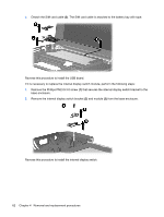
9. Grasp the system board at its midpoint (1) and lift the right side (2) up. Then remove the system board (3) from the base enclosure. Reverse the procedure to install the system board. Heat sink assembly NOTE: The heat sink assembly spare part kit includes replacement thermal material. Description Heat sink assembly Spare part number 515099-001 Before removing the heat sink assembly, follow these steps: 1. Shut down the device. If you are unsure whether the device is off or in Hibernation, turn the device on, and then shut it down through the operating system. 2. Disconnect all external devices connected to the device. 3. Disconnect the power from the device by first unplugging the power cord from the AC outlet and then unplugging the AC adapter from the device. 4. Remove the battery (see Battery on page 37). 5. Remove the following components: a. Keyboard (see Keyboard on page 40) b. Hard drive or solid-state drive (see Mass storage devices on page 42) c. Top cover (see Top cover on page 45) d. WLAN module (see WLAN module on page 48) Remove the heat sink assembly: 1. Remove the two Phillips PM1.6×2.5 screws (1) that secure the heat sink assembly to the system board. Component replacement procedures 57
-
 1
1 -
2
-
3
-
4
-
5
-
6
-
7
-
8
-
9
-
10
-
11
-
12
-
13
-
14
-
15
-
16
-
17
-
18
-
19
-
20
-
21
-
22
-
23
-
24
-
25
-
26
-
27
-
28
-
29
-
30
-
31
-
32
-
33
-
34
-
35
-
36
-
37
-
38
-
39
-
40
-
41
-
42
-
43
-
44
-
45
-
46
-
47
-
48
-
49
-
50
-
51
-
52
-
53
-
54
-
55
-
56
-
57
-
58
-
59
-
 60
60 -
 61
61 -
 62
62 -
 63
63 -
 64
64 -
 65
65 -
 66
66 -
 67
67 -
 68
68 -
 69
69 -
 70
70 -
71
-
72
-
73
-
74
-
75
-
76
-
77
-
78
-
79
-
80
-
81
-
82
-
83
-
84
-
85
-
86
-
87
-
88
-
89
-
90
-
91
-
92
-
93
-
94
-
95
-
96
-
97
-
98
-
99
-
100
-
101
-
102
-
103
-
104
-
105
-
106
-
107
-
108
-
109
-
110
-
111
-
112
-
113
-
114
-
115
-
116
-
117
-
118
-
119
-
120
-
121
 |
 |