HP Model 748 HP Model 748 Service Handbook
HP Model 748 - VME Workstation Manual
 |
View all HP Model 748 manuals
Add to My Manuals
Save this manual to your list of manuals |
HP Model 748 manual content summary:
- HP Model 748 | HP Model 748 Service Handbook - Page 1
Service Handbook Model 748 HP Part No. A4511-90605 Edition E1199 Special Online Edition Printed in U.S.A. - HP Model 748 | HP Model 748 Service Handbook - Page 2
© Hewlett-Packard Co. 1997, 1999 Printing History First Printing: February 1997 Latest Printing: November 1999 UNIX is a registered trademark of The Open Group. NOTICE The information contained in this document is subject to change without notice. HEWLETT-PACKARD MAKES NO WARRANTY OF ANY KIND WITH - HP Model 748 | HP Model 748 Service Handbook - Page 3
Statements Safety See the owner's guide that came with your system for emission to protect radio and television reception. All HP nodes and peripherals have been tested and comply not installed and used in accordance with the instruction manual, may cause harmful interference to radio communications. - HP Model 748 | HP Model 748 Service Handbook - Page 4
Safety and Regulatory Statements In the event that a third-party noncompliant I/O device is installed, the customer assumes all responsibility and liability arising therefrom. Electrostatic Discharge (ESD) Precautions Electrostatic charges can damage the integrated circuits on printed circuit boards - HP Model 748 | HP Model 748 Service Handbook - Page 5
) Slot 1-6 PMC Expansion 1-6 Built-In Interfaces 1-6 Model 744 System Board Interfaces 1-7 Hardware Architecture 1-10 Operating Systems 1-10 HP-UX 1-10 Product Identification 1-12 Technical Information 1-13 Support 1-14 Hardware Support 1-15 Field Repair Philosophy 1-15 2 Environmental/Installation - HP Model 748 | HP Model 748 Service Handbook - Page 6
4-2 Diagnostic Overview 4-3 Diagnostic Documentation 4-3 Board Computer Troubleshooting 4-4 5 Field Replaceable Units Introduction 5-2 Tools Required 5-2 Safety Precautions 5-2 New Parts 5-3 Exchange Parts 5-3 Local Hewlett-Packard Sales & Service Office 5-4 Replaceable Parts 5-4 Mass Storage Module - HP Model 748 | HP Model 748 Service Handbook - Page 7
Contents VME Module 5-13 Model 743/744 VMEbus Board Computer Parts 5-14 Removing and Replacing Mass Storage Devices 5- Removal 5-30 VME Module Removal 5-31 Preliminary Requirements 5-31 Procedure to remove VME Module 5-32 VME Backplane Removal 5-33 Power Supply and Chassis Parts Replacement 5-34 vii - HP Model 748 | HP Model 748 Service Handbook - Page 8
Preliminary Requirements 5-34 Power Supply Removal 5-35 Power Switch Assembly 5-36 Power Distribution PCA 5-37 6 Diagrams Functional Description of Model 748 Chassis 6-2 7 Reference Documentation Service Documentation 7-2 System Installation and Getting Started Documentation 7-4 8 Service Notes viii - HP Model 748 | HP Model 748 Service Handbook - Page 9
Workstation 1-3 I/O Connector Panel 1-7 Serial Number Information 1-12 Model 744 Memory Slots 3-4 Model 748 Exploded View 5-4 SE Mass Storage Module Parts 5-5 FWD Mass Storage Module Parts 5-7 EISA and PCI Module Parts 5-9 Chassis and Power Supply Parts 5-11 VME Module - HP Model 748 | HP Model 748 Service Handbook - Page 10
Contents Tables Model 748 Ruggedized Workstation Features 1-4 Supported Monitors for Model 748 1-6 Supported PMC Graphics Upgrades 1-6 Supported AUI LAN Adapters and Devices 1-9 Supported 700/RX Family X-Terminals 1-9 HP-UX Operating Systems and Languages 1-11 Electrical Information 1-13 Physical - HP Model 748 | HP Model 748 Service Handbook - Page 11
1 Product Information 1-1 - HP Model 748 | HP Model 748 Service Handbook - Page 12
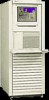
introduces the Model 748 workstation. The Model 748 uses the Model 744 board computer in one of the following configurations: Model 748/132L ruggedized workstation Model 748/165L ruggedized workstation Figure 1-1 shows the Model 748 workstation, and Table 1-1 lists the Model 748 workstation features - HP Model 748 | HP Model 748 Service Handbook - Page 13
Product Information Product Description Figure 1-1 Model 748 Ruggedized Workstation 1-3 - HP Model 748 | HP Model 748 Service Handbook - Page 14
interfaces Graphics Mass storage module VME module EISA module PCI module Power supply Model 748 Ruggedized Workstation Features Functionality HP-UX 132 MHz PA-RISC 7300LC in Model 748/132L 165 MHz PA-RISC 7300LC in Model 748/165L Battery-backed Real-Time Clock Bus error timer 1 RAM stack Maximum - HP Model 748 | HP Model 748 Service Handbook - Page 15
back out are supported. Power switching has both front and back accessibility. Status and test LEDs are located on the Model 744 VMEbus RAM board. 32 MB is the minimum required for the HP-UX operating system. Memory boards are designed to be stacked in the single stack available on a Model 744. - HP Model 748 | HP Model 748 Service Handbook - Page 16
Kit) Slot Model 748 ruggedized workstation computers support GSC upgrades. PMC Expansion The Model 748 accepts the PMC expansions available for the Model 744 board computer. Table 1-3 shows the supported PMC graphics upgrades. Table 1-3 Supported PMC Graphics Upgrades Product Number HP A4979A - HP Model 748 | HP Model 748 Service Handbook - Page 17
full descriptions including pin-I/O information consult the appropriate model owner's guide and service handbook. Figure 1-2 I/O Connector Panel Small Computer are supported on the RS-232 interface connectors. The A connector is used for the console. HP Parallel Interface. A 25-pin HP Parallel - HP Model 748 | HP Model 748 Service Handbook - Page 18
for the PS/2 keyboard and mouse. The keyboard and mouse are part of localization kit HP A4030A. Local Area Network Interface. The IEEE 802.3 Ethernet Local Area Network (LAN) circuit connector is installed. Table 1-4 lists the supported LAN adapters and other network devices. Table 1-5 lists - HP Model 748 | HP Model 748 Service Handbook - Page 19
HP 28683A Fiber Optic Transceiver HP 28682A Fiber Optic Hub Plus HP 28684A EtherTwist Hub Table 1-5 Supported 700/RX Family X-Terminals Product Number Product Name HP C2701A HP C2702A HP C2704A HP C2705A HP C2706A HP C2709A HP for input. EISA Module. The Model 748 has a 4-slot EISA module. 1-9 - HP Model 748 | HP Model 748 Service Handbook - Page 20
board. Operating Systems HP-UX HP-UX 10.20 (or later) is supported on the Model 748 Ruggedized Workstations with the Model 744 as the board computer. HP-UX 9.05 (or later) is supported on the Model 748 Ruggedized Workstations with the Model 743 as the board computer. The Model 748 is booted from an - HP Model 748 | HP Model 748 Service Handbook - Page 21
Systems Foundation (OSF). ISU Test and Measurement Software Standard Instrument Control Library (SICL)Rocky Mountain Basic/UX VEE ISU Languages C/ ANSI C FORTRAN 9000 Pascal HP C + + C + + Developer ISU User Interface and Graphics Libraries HP GKS X11R5 Motif 1.2 VUE 3.0 Architect 2.0 1-11 - HP Model 748 | HP Model 748 Service Handbook - Page 22
Product Information Product Identification Product Identification On the bottom, a label lists the product serial number. Its information can be interpreted as shown in Figure 1-3 below for an example serial number 6247A00001: Figure 1-3 Serial Number Information 1-12 - HP Model 748 | HP Model 748 Service Handbook - Page 23
. Official specifications are listed in the system's Technical Data Sheet. Table 1-7 shows electrical information. Table 1-7 Electrical Information Power consumption Model 748; 1080 watt Line voltage Line frequency 90 - 132 Volts 180 - 264 Volts 50 - 60 Hz Table 1-8 lists the EISA - HP Model 748 | HP Model 748 Service Handbook - Page 24
condensation. Table 1-9 lists the Model 748 physical information. Table 1-9 Physical Information Rack mount units 7 high Height: 312.0 mm (12.22-in.) Width: 425 mm (16.75-in.) Depth: 412.6 mm (16.24-in.) Weight: 29.0 kg (60.0 pounds) Support Support services and policies mentioned in - HP Model 748 | HP Model 748 Service Handbook - Page 25
. Repair Services Hewlett-Packard supports three repair services: Return to Hewlett-Packard Repair On-Site Repair Customer Repair For Return to Hewlett-Packard Repair, customers return the product to their local HP Sales and Service Office, where an HP Bench Repair Engineer troubleshoots, and - HP Model 748 | HP Model 748 Service Handbook - Page 26
Product Information Technical Information 1-16 - HP Model 748 | HP Model 748 Service Handbook - Page 27
2 Environmental/ Installation/PM 2-1 - HP Model 748 | HP Model 748 Service Handbook - Page 28
Environmental/Installation/PM Overview Overview This chapter lists the environmental specifications and regulatory requirements for the system. Installation and preventive maintenance information, if applicable, is also provided. 2-2 - HP Model 748 | HP Model 748 Service Handbook - Page 29
Operating temperature 0° - 55° C (without mass storage) 5° - 40° C (with mass storage) Non-operating temperature -40° - 71° C Heat dissipation Model 748i; 1,836 BTU, 464 Kcal/hr Model 748i; 3,672 BTU, 928 Kcal/hr Humidity (non-condensing); 95% maximum at 40° C (without mass storage - HP Model 748 | HP Model 748 Service Handbook - Page 30
Environmental/Installation/PM Regulatory Requirements Regulatory Requirements Table 2-2 lists the regulatory requirements for this workstation. Table 2-2 Regulatory Information Safety Specification: UL 1950, CSA 22.2 950-M, TUV EN60950, Finland TSH, EMKO TUE(74) DK203, Sweden's SS4361450 Laser - HP Model 748 | HP Model 748 Service Handbook - Page 31
Environmental/Installation/PM Installation Installation Refer to Model 748 Owner's Guide for system installation information. 2-5 - HP Model 748 | HP Model 748 Service Handbook - Page 32
Environmental/Installation/PM Preventive Maintenance Preventive Maintenance The system unit requires no preventive maintenance. Some removable media storage devices require operator preventive maintenance. Refer to Model 748 Owner's Guide for more information. 2-6 - HP Model 748 | HP Model 748 Service Handbook - Page 33
3 Configuration 3-1 - HP Model 748 | HP Model 748 Service Handbook - Page 34
744 VMEbus Board Computer, • Mass storage devices, • VME, EISA, or PCI accessory cards • Standard internal printed circuit boards The Model 748 ruggedized workstation uses two power supplies. Each power supply provides voltages to the workstation modules and accessory card slots as listed in Table - HP Model 748 | HP Model 748 Service Handbook - Page 35
power needs, follow these instructions: 1 Determine the board Model 744 memory cards, you will need to use Figure 3-1 and Table 3-1 (for Model 744/132L) or Table 3-2 (for Model other memory cards in the system would be inactive), followed by two 32 MB cards in slots 0, 1, or 2 (all other memory - HP Model 748 | HP Model 748 Service Handbook - Page 36
744 Memory Slots Table 3-1 Model 744/132L Memory Card Current Usage Worksheet Memory Card Size First Active Bank1 Second Active Bank Third Active Bank Inactive Banks Totals (+5V) 32 MB2 1.15 A 1.15 A 1.15 A 0.05A x ___ _________ 64 MB 2.6 A N/A N/A 0.1 A x ___ _________ 128 MB - HP Model 748 | HP Model 748 Service Handbook - Page 37
Configuration Power Budgeting Table 3-2 Model 744/165L Memory Card Current Usage Worksheet Memory Card Size First Active Bank1 Second Active Bank Third Active Bank Inactive Banks Totals (+12V) Totals (+5V) 32 MB2 0.53 A 0.53 A 0.53 A 0.023A x 12V) 64 MB 1.2 A N/A N/A 0.05 A x (+12V) - HP Model 748 | HP Model 748 Service Handbook - Page 38
Configuration Power Budgeting 3 Write in the board computer's concurrent requirements in the line provided for VME slots 1 and 2 in the Lower Power Supply Worksheet (Table 3-7). 4 Determine each device's current requirements from the Internal Device Requirements table and the VME accessory card's - HP Model 748 | HP Model 748 Service Handbook - Page 39
9A each = FWD SCSI GSC card x 0.7A each = HCRX graphics board 2.0A PMC bridge adapter 0.6A PMC cards on bridge adapter 3 Totals for Model 744 board computer 1. Does not include on-board graphics, if installed. 2. On-board graphics and graphics accessory cards are each separate graphics - HP Model 748 | HP Model 748 Service Handbook - Page 40
7A each = FWD SCSI GSC card x 0.7A each = HCRX graphics board 2.0A PMC bridge adapter 0.6A PMC cards on bridge adapter 3 Totals for Model 743 board computer 1. Does not include on-board graphics, if installed. 2. On-board graphics and graphics accessory cards are each separate graphics - HP Model 748 | HP Model 748 Service Handbook - Page 41
drive 4 GB SE hard drive 9 GB FWD hard drive Hewlett-Packard EISA Cards: HP 25525A SCSI DIFF HP 25525B EISA SCSI HP 25560A HPIB HP 25567A LAN HP J2156A FDDI HP J2159A X.25 PSI HP J2165A LAN HP J2645AA VG Any LAN HP J2802B ATM +5.1V dc +12V dc Amps Amps -12V dc Amps 1.6 A 1.0 A 0.8 A 1.2 A 1.1A - HP Model 748 | HP Model 748 Service Handbook - Page 42
Current Required: Maximum Available: 34.0A 8.0A 1.5A 1. +3.3 current must be entered into Table 3-3 or Table 3-4 CAUTION: If you upgrade your Model 748 ruggedized workstation, adding more: RAM cards, mass storage devices, GSC, VME, EISA, PCI, or PMC accessory cards, you must recompute the - HP Model 748 | HP Model 748 Service Handbook - Page 43
2 EISA/PCI Slot 3 EISA/PCI Slot 4 Lower Power Supply Current Budgeting Worksheet Device +5V dc +12V dc -12V dc -5.2V dc Amps Amps Amps Amps Model 743/ 744 Board Computer _______ Total Current Required: Maximum Available: 33.0A 8.0A 1.5A 1.0A 3-11 - HP Model 748 | HP Model 748 Service Handbook - Page 44
Configuration Power Budgeting 3-12 - HP Model 748 | HP Model 748 Service Handbook - Page 45
4 Troubleshooting 4-1 - HP Model 748 | HP Model 748 Service Handbook - Page 46
Consult the appropriate Service Handbook for the model you are working with for specifics on the various tools and tests for that model. Diagnostic Philosophy The diagnostic philosophy is to support the repair strategy. As a result, the goal of the troubleshooting process is to isolate a problem to - HP Model 748 | HP Model 748 Service Handbook - Page 47
Troubleshooting After you have all answers possible, decide what's the most probable cause of the problem of diagnostics are available for the Model 743\744: • Selftests are system. • Offline diagnostics are on the Support Tape, a separate tape or CD-ROM manuals that provide complete information. 4-3 - HP Model 748 | HP Model 748 Service Handbook - Page 48
Introduction to Troubleshooting Table 4-1 Diagnostic Documentation Manual Title Part Number HP 9000 Series 700i/rt Model 743 Board Computer Service Handbook Model 744/132L Board Computer Service Handbook Support Tools Manager User's Manual; HP 9000 Series 700 and 800 HP 9000 Series - HP Model 748 | HP Model 748 Service Handbook - Page 49
5 Field Replaceable Units 5-1 - HP Model 748 | HP Model 748 Service Handbook - Page 50
Field Replaceable Units Introduction Introduction This chapter contains the procedures to replace assemblies in the VMEbus Board Computer and the Model 748i chassis components (such as the VME module, EISA/PCI module, Mass Storage module, Power supplies and chassis mounted hardware). CAUTION: - HP Model 748 | HP Model 748 Service Handbook - Page 51
and exchange part. Exchange parts only are available direct from: Support Materials Organization Hewlett-Packard Company 8050 Foothills Boulevard Roseville, California 95678 USA Telephone: (916) 786-8000 Support Material & Services Europe Hewlett-Packard Ltd. Filton Road - Stoke Gifford Bristol - HP Model 748 | HP Model 748 Service Handbook - Page 52
Field Replaceable Units Introduction Local Hewlett-Packard Sales & Service Office Name: Address: City, State, Zip: Tel. Number: Replaceable Parts Figure 5-1 shows an exploded view of the Model 748 workstation. Figure 5-1 Model 748 Exploded View 5-4 - HP Model 748 | HP Model 748 Service Handbook - Page 53
5 Mass Storage Module Parts Figure 5-1 and Figure 5-2 show exploded views of the Single-Ended (SE) and Fast-WideDifferential (FWD) mass storage modules. 2 1 3 Figure 5-1 SE Mass Storage Module Parts Table 5-2 is a SE mass storage module parts list. 5-5 - HP Model 748 | HP Model 748 Service Handbook - Page 54
Table 5-1 Model 748 SE Mass Storage Module Parts List Ref Exchange No. Part Number New Part Number Description Notes 1 A1094-69007 A2084-69001 A2084-69002 A1658-69108 A1658- - HP Model 748 | HP Model 748 Service Handbook - Page 55
1 2 Figure 5-2 FWD Mass Storage Module Parts Table 5-2 is a FWD mass storage module parts list. 5-7 - HP Model 748 | HP Model 748 Service Handbook - Page 56
Table 5-2 Model 748 FWD Mass Storage Module Parts List Ref Exchange No. Part Number New Part Number Description Notes 1 A1094-69007 A1658-69016 A2084-69016 A1658-69010 A1658- - HP Model 748 | HP Model 748 Service Handbook - Page 57
EISA and PCI Module Parts The EISA and PCI trays are similar modules, with the exception of the interface modules. Figure 5-3 shows an exploded view of the EISA or PCI module parts. 2 1 3 4 Figure 5-3 EISA and PCI Module Parts 5-9 - HP Model 748 | HP Model 748 Service Handbook - Page 58
Table 5-3 is an EISA and PCI module parts list. Table 5-3 Model 748 EISA and PCI Module Parts List Ref No. Exchange Part Number New Part Number Description 1 A4309-62005 EISA Assembly A4505-66001 PCI Assembly 2 A4309-66001 - HP Model 748 | HP Model 748 Service Handbook - Page 59
Chassis and Power Supply Parts Figure 5-4 shows an exploded view of the Model 748 chassis and power supply. 2 1 3 Figure 5-4 Chassis and Power Supply Parts 5-11 - HP Model 748 | HP Model 748 Service Handbook - Page 60
and power supply parts list. Table 5-4 Model 748 Chassis and Power Supply Parts List Ref No. Exchange Part Number New Part Number Description 1 A4309-87901 Chassis 2 A4309-66002 Power Distribution PCA 3 0950-2303 - HP Model 748 | HP Model 748 Service Handbook - Page 61
VME Module Figure 5-5 shows an exploded view of the VME module. 2 1 Figure 5-5 VME Module Parts 5-13 - HP Model 748 | HP Model 748 Service Handbook - Page 62
VME module parts list. Table 5-5 Model 748 VME Module Parts List Ref No. Exchange Part Number New Part Number Description 1 A2636-00004 VME Cover Plate 2 A4309-66003 VME Backplane Notes Model 743/744 VMEbus Board Computer Parts Consult the appropriate model Service Handbook for parts and - HP Model 748 | HP Model 748 Service Handbook - Page 63
and replacement instructions for mass storage devices • Device addressing and location Introduction Instructions for removing the Operating System. 4 Refer to the owner's guide, for information on properly shutting down HP-UX. 5 Turn off power to the Model 748. 6 Set up a static-free work place - HP Model 748 | HP Model 748 Service Handbook - Page 64
Removing and Replacing Mass Storage Devices Removing Mass Storage Module CAUTION: The mass storage module can weigh about 10 lbs, and may be awkwardly balanced. Use care when handling the module, as dropping it could damage the mass storage devices! NOTE: All Installation procedures are the - HP Model 748 | HP Model 748 Service Handbook - Page 65
Removing and Replacing Mass Storage Devices Selecting Device Address Procedure 1 Unpack the device. 2 Set only jumpers or switches that are required to change the device SCSI address, any others should remain as shipped. The default SCSI addresses for devices is shown in Table 5-6. You should - HP Model 748 | HP Model 748 Service Handbook - Page 66
Removing and Replacing Mass Storage Devices CD-ROM Figure 5-7 and Figure 5-8 show the CD-ROM disk drive address settings. SCSI Jumpers SCSI ID 0 1 2 3 4 SCSI ID 5 6 Figure 5-7 Early Model CD-ROM Disk Drive 5-18 - HP Model 748 | HP Model 748 Service Handbook - Page 67
Removing and Replacing Mass Storage Devices Figure 5-8 Later Model CD-ROM Disk Drive 5-19 - HP Model 748 | HP Model 748 Service Handbook - Page 68
Removing and Replacing Mass Storage Devices Floppy Disk Drive Figure 5-9 shows the floppy disk drive address settings. ID2 ID1 ID0 Target SCSI ID Jumpers 0 1 2 3 4 5 6 ID2 ID1 ID0 Figure 5-9 Floppy Disk Drive 5-20 - HP Model 748 | HP Model 748 Service Handbook - Page 69
DDS Tape Drive Figure 5-10 shows the DDS tape drive address settings. 1 1 TERM PWR SCSI 2 SCSI 1 SCSI 0 - NC Figure 5-10 SCSI ID 0 1 2 3 SCSI ID 4 5 6 DDS Tape Drive Address Selection 5-21 - HP Model 748 | HP Model 748 Service Handbook - Page 70
Figure 5-11 Later Model DDS Tape Drive Address Selection 5-22 - HP Model 748 | HP Model 748 Service Handbook - Page 71
for jumper settings and any applicable software patch dependencies. Device Locations in Tray Figure 5-12 through Figure 5-16 show the possible device locations for the Model 748 workstation. Figure 5-12 Device Locations 1 of 4 5-23 - HP Model 748 | HP Model 748 Service Handbook - Page 72
Figure 5-13 Device Locations 2 of 4 5-24 - HP Model 748 | HP Model 748 Service Handbook - Page 73
Figure 5-14 Device Locations 3 of 4 5-25 - HP Model 748 | HP Model 748 Service Handbook - Page 74
Figure 5-15 Device Locations 4 of 4 5-26 - HP Model 748 | HP Model 748 Service Handbook - Page 75
Figure 5-16 FWD Device Locations 5-27 - HP Model 748 | HP Model 748 Service Handbook - Page 76
Mass Storage Device Removal NOTE: When replacing a floppy disk drive, you may need to add or replace a bezel. Procedure Power & SCSI cables • Disconnect both the power and SCSI cables connected to the device. Retaining screws • Loosen the four screws holding the device in the tray. Device removal - HP Model 748 | HP Model 748 Service Handbook - Page 77
PCI Module Removal Preliminary Requirements 1 Shut down any applications. 2 Shut down the OS. Refer to the owner's guide for information on properly shutting down HP-UX. 3 Turn power off to the Model 748. 4 Set up a static-free work place to handle the EISA or PCI card cage. 5 Disconnect power cords - HP Model 748 | HP Model 748 Service Handbook - Page 78
PCI Module Removal EISA or PCI Converter Board and Backplane Removal 1 Remove any cards installed in cage. 2 In an EISA card cage, remove the two HP HIL connector screws (1 in Figure 5-19) lo- cated on the front of the cage to free the connector. 3 Remove the screw (2 in Figure 5-19) on - HP Model 748 | HP Model 748 Service Handbook - Page 79
can be removed! Preliminary Requirements 1 Shut down any applications. 2 Shut down the OS. Refer to the owner's guide for information on properly shutting down HP-UX. 3 Turn off power to the Model 748. 4 Set up a static-free work place to handle the VME card cage. 5 Disconnect power cords. 6 Remove - HP Model 748 | HP Model 748 Service Handbook - Page 80
VME Module Removal Procedure to remove VME Module 1 Remove all external cables connected to the 743/744 VMEbus computer(s) and any other VME card. 2 Loosen captive screws (located in handles of cage) 3 Slide VME card cage out of unit. 4 Place cage on static mat. 5-32 - HP Model 748 | HP Model 748 Service Handbook - Page 81
VME Module Removal NOTE: If VME backplane is to be removed, all VME Cards must be removed prior to cage removal. VME Backplane Removal 1 Remove VME card cage as directed in previous steps. 2 Place the VME card cage on static mat with the EISA connector facing up. 3 Remove the three screws on the - HP Model 748 | HP Model 748 Service Handbook - Page 82
: Power Supply(s) Power Distribution PCA Power Switch Assembly Preliminary Requirements All procedures in this section require the following: OS shutdown Power removed from the Model 748 Power cords removed from power supplies Ground wires removed from power supplies (M4 grounding points) 5-34 - HP Model 748 | HP Model 748 Service Handbook - Page 83
Power Supply and Chassis Parts Replacement Power Supply Removal Retaining Screw 1 Remove power cord(s) and ground wire(s) connected to power supply. 2 Loosen retaining screw. 3 Slide out power supply. 4 Repeat process to remove other supply. 5-35 - HP Model 748 | HP Model 748 Service Handbook - Page 84
previously directed. 2 Disconnect the power switch assembly connector from the power distribution PCA. Figure 5-20 Magnified View of Power Switch Tabs 3 Spread the Power Switch support bracket tabs outward, as shown in Figure 5-20. 4 Remove Switch. 5-36 - HP Model 748 | HP Model 748 Service Handbook - Page 85
Power Supply and Chassis Parts Replacement Power Distribution PCA 1 Remove the EISA and VME card cages following the procedures given in this chapter. 2 Remove both power supplies following the procedures given in this chapter. 3 As shown in Figure 5-21, loosen the thumb screw, then slide the power - HP Model 748 | HP Model 748 Service Handbook - Page 86
Power Supply and Chassis Parts Replacement 4 Rotate lower edge of the center wall to the right about 2 inches, then slide tabs at the top of the wall out of slots in the mass storage module support. Refer to Figure 5-22. Set aside wall. Figure 5-22 Center Wall Removal 5-38 - HP Model 748 | HP Model 748 Service Handbook - Page 87
Power Supply and Chassis Parts Replacement 5 Loosen captive screw holding the power distribution PCA circuit board to the front of the chassis. Slide board to right to remove. Refer to Figure 5-23. Figure 5-23 Power Distribution PCA Removal from Chassis 5-39 - HP Model 748 | HP Model 748 Service Handbook - Page 88
Power Supply and Chassis Parts Replacement 5-40 - HP Model 748 | HP Model 748 Service Handbook - Page 89
6 Diagrams 6-1 - HP Model 748 | HP Model 748 Service Handbook - Page 90
Description of Model 748 Chassis Functional Description of Model 748 Chassis The Model 748 chassis provides the following: • Two 300-Watt power supplies (one for VME slots 3 to 8, and one for VME slots 1 and 2, Mass Storage, and EISA). • Four slot EISA Card Cage or four slot PCI Card Cage • HP-HIL - HP Model 748 | HP Model 748 Service Handbook - Page 91
7 Reference Documentation 7-1 - HP Model 748 | HP Model 748 Service Handbook - Page 92
references include part numbers of many hardware documents relating to these workstations. Service Documentation Table 7-1 Related Service Documentation Manual Title HP Model 743 Board Computer Service Handbook HP Model 744 Board Computer Service Handbook Part Number A2636-90604 A4511-90603 7-2 - HP Model 748 | HP Model 748 Service Handbook - Page 93
Printers PA-RISC Support Tools Manual Licensed Users Volume 7, Utilities PA-RISC Support Tools Manual Licensed Users Volume 8, ISL Support Tools PA-RISC Support Tools Manual HP Employees Offline Diagnostics Environment (ODE) User's Manual System Exerciser Install and Operating Guide 5961-1612 09740 - HP Model 748 | HP Model 748 Service Handbook - Page 94
Documentation Table 7-3 System Installation and Getting Started Documentation Manual Title Model 743 Board Computer Owner's Guide Model 744 Board Computer Owner's Guide HP-UX 9.05 VME Configuration and Driver Development Guide VME Services for HP-UX 10 Part Number A2636-90603 A4511-90606 A2636 - HP Model 748 | HP Model 748 Service Handbook - Page 95
8 Service Notes . 8-1 - HP Model 748 | HP Model 748 Service Handbook - Page 96
Service Notes Place service notes here. 8-2 - HP Model 748 | HP Model 748 Service Handbook - Page 97
offline, 4-3 online, 4-3 documentation diagnostic, 7-3 installation, 7-4 service, 7-2 E EISA converter board removal, 5-30 EISA module, H hard disk drive SCSI settings, 5-23 heat dissipation, 2-3 height, 1-14 HP-HIL, 1-7 HP-UX, 1-10 humidity, 2-3 I installation, 2-5 L LAN adapters, 1-9 LAN interface - HP Model 748 | HP Model 748 Service Handbook - Page 98
ID, 5-17 hard disk drives, 5-23 selftests, 4-3 serial interface, 1-7 serial number, 1-12 service documentation, 7-2 service notes, 8-2 support, 1-14 T technical information, 1-13 tools, 5-2 troubleshooting, 4-2 board computer, 4-4 V VME backplane removal, 5-33 VME module, 1-4, 1-10, 5-13 removal
-
 1
1 -
 2
2 -
 3
3 -
 4
4 -
 5
5 -
 6
6 -
 7
7 -
8
-
9
-
10
-
11
-
12
-
13
-
14
-
15
-
16
-
17
-
18
-
19
-
20
-
21
-
22
-
23
-
24
-
25
-
26
-
27
-
28
-
29
-
30
-
31
-
32
-
33
-
34
-
35
-
36
-
37
-
38
-
39
-
40
-
41
-
42
-
43
-
44
-
45
-
46
-
47
-
48
-
49
-
50
-
51
-
52
-
53
-
54
-
55
-
56
-
57
-
58
-
59
-
60
-
61
-
62
-
63
-
64
-
65
-
66
-
67
-
68
-
69
-
70
-
71
-
72
-
73
-
74
-
75
-
76
-
77
-
78
-
79
-
80
-
81
-
82
-
83
-
84
-
85
-
86
-
87
-
88
-
89
-
90
-
91
-
92
-
93
-
94
-
95
-
96
-
97
-
98
 |
 |

Service Handbook
Model 748
HP Part No.
A4511-90605
Edition E1199
Special Online Edition
Printed in U.S.A.